A new take on hydropower design
15 April 2011The TUM hydro shaft power plant has been developed at the Technical University of Munich. Here members of the project team give more details about this innovative new intake concept for hydropower plants
In many European countries the good sites for hydropower plants have already been utilised but there are still thousands of existing weirs. Some of these were used for hydropower in earlier days, or were built for stabilising river beds, for irrigation or navigation purposes. Such weirs are hindering free migration of fish and macrozoobenthos and therefore have to be modified due to European legislation in the Water Framework Directive (WFD). All weirs of more than 0.3m in height must be refurbished. The height ranges of such weirs include thousands of sites with head differences of more than 1m up to several metres. Whether such sites will be used for small hydropower is dependent on economic factors along with ecological demands which have to be satisfied by a newly designed hydropower plant.
At Technische Universität München (the Technical University of Munich – TUM) a simple, very economic, ecological and low-maintenance hydropower design, the TUM-hydro shaft, has been invented. This can be an attractive proposal for using existing weir sites with small heads for generating CO2 free electricity and helping fish migration through an eco-corridor. In contrast to common designs the TUM-hydro shaft power plant switches the intake plane from nearly vertical to horizontal and a parallel bed. It renounces a stream shaped intake design to reduce costs and makes up for this disadvantage by a large cross sectional area and therefore low velocities. As such it is also possible to work with small trash rack bar interdistances prohibiting fish from entering into the turbines or being pressed to the metal bars and therefore hurt or even killed. Additionally the innovative design offers fish a suitable path for downstream migration.
New concept
Over the years river hydro power plants have been a matter of individual prototype design. Depending on the situation, the topography, the discharge, the head difference, the turbines used etc, the design of the power plant has been customised. Several major design variants have become standards mainly distinguished by the water course. Is there a shorter or longer headrace and tailrace channel diverting the flow out of, through the plant and back into the riverbed, or does the plant position in the river course and weir structure enhance the required head and the possibility to spill the water during floods? Common to most designs is the intake section which is a nearly vertical section with a vertical trash rack and with trash rack cleaning machines. The hydraulic machines are usually positioned in an accessible power house. For smaller heads however this design is, apart from being cost expensive, not well suited for several reasons:
• Due to the small head the vertical and almost quadratic cross sections require deep foundations and are therefore expensive.
• The deep inlet sill may be subject to sedimentation or expensive preventive measures have to be provided especially in rivers where extensive bed-load transport occurs.
• Often land is required for the power house, which may be difficult due to civilisation, nature or monument conservation.
• The plant changes the aesthetics of the site and produces additional noise.
These aspects gave rise to the creation of a completely new small hydro concept with the requirements of being cost and maintenance effective, being invisible and not audible, being without major impact to the river courses, their morphology and their fauna. Such a design therefore had to be positioned in the river course, with power house, turbines and generators below the water surface fitted into the river bed and with the possibility to bypass bed-load material and fish without harm around the turbines.
Cost optimisation
In order to reduce costs in general, construction costs, maintenance costs and the efficiency of production have to be optimised. For construction costs the important points are modularisation, easy and fast construction, as well as including time for getting permissions for the plant. The geometries of the concrete works should be very simple. It should be possible to construct in the river without a major and completely sealed excavation pit, while mounting the machines should be an easy and quick step.
Think of constructing a simple box (the power plant) with vertical walls in the river bed just upstream of an existing weir, possibly using drill or sheet piles and using injection to seal the box from below. Think of just lowering both a hydraulic machine directly coupled with a submersible generator into this box. Now this box would of course require a horizontal and bed plane trash rack and would, you could argue, have incredible flow losses due to the poorly shaped transition from the intake section to the turbines. But what if you allow the velocities to be low and therefore the hydraulic losses, would it be possible to compensate for the disadvantages? You would require a slightly new type of hydraulic machine - but several machines are on the market or could simply be modified in order to fit the requirements. One possible machine is the so-called Dive turbine which can be characterised as a Kaplan turbine without flexible blades but with adjustable guide vanes and adjustable rotational speed and a permanent magnet generator. The machine has comparable efficiency to classical Kaplan turbines but is, due to the fixed blades, very robust. Due to a patented sealing concept it can be just set onto a fixed metal seat without complex mounting.
The only disadvantage of the outlined concept is the accessibility. Due to the underwater setup of the mechanics, the hydro machinery and the generator access has to be achieved by setting mobile stop logs to prevent water access and by using cranes. Due to this disadvantage low maintenance requirements are compulsory.
At a site under investigation, with an existing weir structure, it could be shown that such concrete volumes can be reduced to 20% compared with a conventional design. We therefore expect that the TUM hydro shaft power plant can be produced to a price reduced by some 30% to 50% compared with conventional plants.
We also expect very low maintenance efforts due to robust techniques provided by the turbine manufacturers. An additional cost reduction can be expected with another type of turbine possessing horizontal axis and suction pipe. For this case the shaft will be less deep and therefore less costly. The concept with horizontal axis could reduce the necessary head to achieve cost efficiency to probably 1.5m or so.
Ecology and aesthetics
As already imposed by economic arguments the concrete box will sit below the water surface and will therefore have neither concrete nor steel parts above the water surface. A new type of turbine, basically being very similar to the wind turbine setup with respect to the drive and generator mechanism, will sit also in the water and will not require its own specially constructed power house. The generator will be cooled by the flowing water and will not have visible nor acoustically recognisable parts.
If we imagine the box to sit just upstream of an existing weir, cutting through it and allowing the water to be diverted through the turbine from the upstream into the downstream water, we see that the water course of the natural river is only diverted through the weir structure instead of overflowing it. Apart from that it remains basically unchanged. Also there will not be any effect on the flow velocities because the weir sill will be the hydraulic element determining water level and flow velocity in the upstream river course. Therefore the box-type hydropower plant will not have any additional, negative effect on flora and fauna of the river. If we succeed to save fish from entering into the power intake with the possibility for downstream migration, and if we can offer an ecological corridor where they can freely migrate upstream, we will be able to improve the existing situation considerably. To protect fish we need a trash rack which mechanically prevents them from entering into the intake. In addition we require velocities low enough to allow them to lift with their own force from the steel bars once pressed to it by accident. Both aspects can be handled if the velocities are chosen to be low.
If we choose an average intake velocity of only 0.3m/sec the velocity head is only about 10% of that when using a standard of 1m/sec average intake velocity. This means that the losses in the trash rack and the inlet structure could be comparable with the big advantage that we can offer on ideal fish protection. The only additional point required for a fish friendly design is the migration of fish from upstream to downstream, which requires an additional bypass of flow around the turbine being visible to fishes willing to migrate downstream.
Sediment and floating debris management
From a sustainability point of view bed-load and suspended particles should be able to be diverted downstream in order to prevent negative effects on morphology and bed erosion. If we are looking at the design described above we can imagine that the shear stresses over the horizontal trash rack are undisturbed compared with the original situation. Additional shear forces can even be mobilised if a gate downstream of the intakes can be lowered for flood situations. Thus, not only improving the sediment diversion but also increasing the capacity of the constructed and existing weir. Depending on the installed turbine and the head difference, gravels of less than 20mm in diameter may be allowed to pass the turbine without damage or erosion of the blades. If this is not possible a flushing channel for gravel can be built around the intake box.
Trash rack cleaning has to be provided in order to remove floating material from the trash rack. Several option are possible and all of these options should be arranged under water with all mechanical parts sitting in the shaft beneath the trash rack in order to be protected by mechanical impacts through stones and floating trees etc.
TUM hydro shaft design
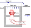
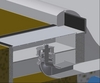
Consideration of the above requirements led to the TUM hydro shaft design illustrated in figure 1. The illustration shows the concrete box, sitting just upstream of an existing weir. It also shows the sliding gate which is, during regular operation partly overflown by water in order to prevent air entraining vortices and enabling fish to migrate downstream. The shaft in figure 1 is equipped with a Dive turbine with propeller, runner and generator sitting below the water surface.
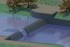
The figure shows how the flow is directed from the horizontal into the vertical shaft portion, through the turbine and then through the suction pipe into the downstream river section. The suction pipe may be constructed from steel, wood or from concrete. A more artistic view is presented in figure 2. It shows a view of a river section, equipped with an existing weir, with the shaft module lowered into the river bed and with an overfall above the shaft in order to prevent air entraining vortices and allowing fish to migrate downstream.
Investigations
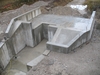
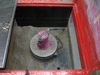
In a research project funded by the German federal ministry for commerce (ZIM project) the TUM hydro shaft design is currently investigated and further developed. The investigation comprises two plants currently under investigation and under construction respectively. The first setup is a 1:5 physical model of the plant built in the laboratory of the Chair for Hydraulic and Water Resources Engineering of TUM, see figure 3. The model is equipped with a fully functional turbine and generator, producing 2kW of electrical power, with a hydraulic operated sliding gate to be raised for trash rack cleaning, and lowered for floods with bed-load transport, and with a trash rack cleaning machine.
The purpose of the 1:5 model tests were the following:
• To measure the hydraulic characteristics of the new design including development of design guidelines for the plant.
• Solve the problem of bed-load transport.
• Investigate vortex prevention of the intake.
The results of the investigation have been very satisfactory. Namely the following could be shown in the 1:5 model:
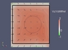
• The shaft intake has a very uniform inlet velocity profile with only minor deviations from the averaged velocity va, ie throughflow divided by cross-sectional area va=Q/A where Q is the discharge of the plant [m3/sec] and A [m2] the cross-sectional area of the shaft inlet (see figure 4).
• The hydraulic losses in the shaft and through the trash rack can be neglected and are within the measuring accuracy of the used devices. The turbine power output being mainly used as a measuring device for comparison of the hydraulic losses of the variants investigated.
• The necessary cross-section in order to achieve velocities which are harmless for fish pressed at the rack can be determined using empirical relations. This is also the case for minimum water depth above the rack in order to prevent major and damaging vortex occurrence.
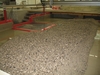
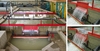
• Sedimentation of the inlet will not occur during regular operation, ie if the turbine is operated during the entire flood event, see figure 5. Even a completely sediment filled shaft could be cleaned off within only a short time if the guide vanes were not completely closed. For redundancy a flushing opening with a valve will be provided. In case of very heavy bed load transport a trash rack could be used which can be completely closed during floods.
• A very simple yet functional trash rack cleaning machine seems to be able to fulfill the desired tasks. However closer investigation on a prototype setup will follow in the near future.
• The TUM hydro shaft power plant may be built as a single shaft or as several shafts may be combined, one beside each other. The flow in the single shaft as well as in a combined multi-shaft is very smooth and better than expected.
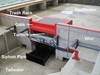
A prototype of the TUM hydro shaft power plant is currently under construction on the laboratory site at TUM and will be investigated until Autumn 2012. It has a head of 2.5m and a discharge of 1.5m3/sec, producing some 30kW of power, see figure 6. The prototype setup will mainly be used to investigate sediment and floating trash as well as fish behaviour. After optimising these issues the power plant should run under real-day conditions without major problems. It is expected that maintenance of the turbine will be necessary after about five years of operation only. This of course requires machines which are especially designed to work with a minimum of maintenance.
Outlook
The TUM hydro shaft design is a very simple and cost-effective new hydro concept. Cost savings of about 30% to 50% depending on the site and the degree of prefabrication and modularisation can be expected. It requires no space outside the river bed is not visible and or audible and offers great options for fish protection and migration.
The behaviour of the design related to flow, losses and sedimentation seems excellent and the challenges of an underwater trash rack cleaning and of flushing options seem manageable.
Prototype sites outside the lab are also being discussed and related projects have been initiated. We expect the first plant to be operational in spring 2013. Some of the investigated sites will have major discharges but lower heads and are therefore more suited for the TUM hydro shaft design using horizontal turbines and suction pipes. Also for some of these possible sites the power output of a single shaft or turbine, which currently ranges from 30kW to about 2MW, is a limiting factor. The use of several shafts must currently serve as a solution even though more powerful machines will be produced in the future.
The authors would like to point to the fact that the presented TUM hydro shaft design has obtained a German patent (DE102009037196B3). Four further German patent applications are pending. For all applications an International patent protection has or will be applied for. The rights on the patents are currently with TUM and possible providers and developers should contact the authors for licence issues.
Besides the current collaboration in the ZIM project with Fella Company of Amorbach, Germany, which manufactures the Dive turbine, collaboration is planned with Voith turbine manufacturers from Heidenheim, Germany. TUM and Voith are currently negotiating on a common cooperation towards a universal hydro concept with a flexible range of application. The main issues of the development are ecological and economical improvements at sites with very low heads. Voith will bring in its expertise from power production in the sea where compact, submerged and robust turbines are required with great reliability.
The authors are P. Rutschmann, A Sepp, F Geiger and J. Barbier from the Institute of Hydraulic and Water Resources Engineering, Technische Universität München, Arcisstr. 21, D-80333, Germany; and S Spiller from NTNU, Department of Hydraulic and Environmental Engineering, Verkstedloftet 234, Klæbuveien 153, N-7491 Trondheim, Norway