CONDITION MONITORING
SMALL HYDRO
Artificial intelligence
29 June 2004Magnus Callavik describes the demonstration project of a new Intelligent Electronic Device with integrated control, protection and communication elements for small hydro
IN RECENT years Swedish electricity prices have increased substantially – on average from US$13.34/MWh to US$33.34-40.01/MWh, and electricity certificates have been introduced to support hydro power units below 1500kW at an additional price level of around US$33.34/MWh. The profitability of, and interest in running, small hydro has increased and interest in renovating existing power stations and starting up new ones has grown.
The value of electricity produced from a 1MW station is still relatively low, so profitable operation requires a stable system that is autonomous to an extent and runs with few unscheduled maintenance and support visits. Systems should have a long life with availability of spare parts, rather than a tailor-made system.
Even for small hydro power plants (<2MW), a relatively large number of functionalities must be included for efficient control and protection as compared to larger power stations. Generally, the requirement to control all of these functionalities requires several building blocks to be included in the plant control system.
Although optimised production is important, the most vital requirement of the station is safe water management and safe protection system. Moreover, if the proportion of distributed versus centralised generation unit connected to the grid grows in the future, the role of the distributed hydro power station as a source for robust grid operation is likely to strengthen, increasing the requirements for protection and interface with the grid.
The objective of this project is to show how a standardised Intelligent Electronic Device (IED) can provide autonomous operation and prioritise safe water management. The IED should be compact and integrated with the control of electrical and mechanical elements including the flow of water, communication, monitoring and protection system for small hydro power plants.
The project was carried out together with one equipment supplier, two electric utilities and the Swedish Energy Authority to focus on: (1) a solution with the minimum functionalities necessary to operate the station and (2) the most important requirements for reliable and cost-effective operation with the highest possible availability.
The final prototype concept will be installed at the Mälarenergi AB-owned 1MW Surahammar power station, installed in 1927 and the 0.9MW Slattefors power station, installed in 1962 and owned and operated by Tekniska Verken i Linköping AB.
Microhydro conceptual approach
The approach is to integrate station monitoring, turbine and generator control functionality into one protection and control IED. Voltage and current signals that are used by the protection unit are also made available to the control system without additional wiring. Integration of functionality into one unit is considered as key to improving cost performance. Communication is a field with rapid development, so the communication module is a separate unit, which can be replaced frequently. It is advisable to use a communication block, based on the iec 61850 standard, with optional remote communication techniques to a remote PC or the operator control room.
Flexible control and protection package
The configuration flexibility of the relay terminals enables protection of any generator, and in particular systems according to the Microhydro concept, where even more functions have to be integrated into one common platform. A Generator Protection Guide describes the applications of individual protection functions and how they are implemented in the ABB 500-series of relay protection terminals. Typical setting guidelines for each protection function are included.
The terminals can be ordered for different mounting arrangements (i.e. 48cm rack, flush, semi-flush, wall mounting etc). The 500 series terminals use a microprocessor based modular platform hardware. The main properties of the modular protection and control terminals are:
• Protection and control terminal is a fully numerical device with low power consumption in the measuring circuits.
• Great flexibility which easily adapts to user practice regarding: protection functions to be included; number of current and voltage inputs required (10 or 20 analogue inputs); number of binary optocoupler inputs required; number of contact outputs needed.
Customer requirements for tripping and external signalling, light emitting diodes (LEDs) to locally indicate status of the unit, starting of protection function and tripping are easily met. Protection and control functions are available as standard/optional software modules and presented to the user as functional blocks. Each individual protective terminal can be provided with a built-in, multicolour 18-LED panel module for visual indicators. Additionally a 40sec, integrated disturbance and event recorder can be provided for monitoring/recording of up to 10 analogue and 48 binary signals per terminal. Alarms for the following operating conditions can be provided as voltage free contacts, local LED indication or remotely via communication: generator frequency deviation (frequency outside pre-set band around rated i.e. ±0.5Hz); generator voltage deviation (voltage outside pre-set band around rated i.e. ±5%); generator loaded/not-loaded; generator negative sequence over-current or over-voltage alarm; generator over-excitation alarm; generator loss-of-field alarm; generator reverse power alarm; VT fuse failure alarm; loss of injection voltage for rotor earth fault protection.
Protection method
Despite monitoring, electrical and mechanical faults sometimes occur, and generators must be provided with protective relays that quickly initiate disconnection of the machine from the system in case of a fault and, where necessary, initiate the shutdown of the generator.
No international standard exists regarding the protective schemes for different generators. Protective configurations may vary from country to country and also between power companies. There are also different needs to consider depending on the specific machine construction. Therefore, generator protective schemes are flexible.
In the Microhydro concept the generator and the step up transformer are protected by common equipment. There is also back-up protection for faults outside the protected zone. In practice, there are many mechanical and thermal protection devices that help avoid damage to the power generating unit. Their output signals typically come to the protection panel as potential-free contacts or mA or voltage signals and incorporated in the overall tripping and alarming scheme via inputs to the terminal.
Control and monitoring
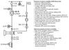
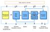
The functionality required for the control of a small hydro power station is provided by function blocks as illustrated in Figure 3. The scope includes control of the water level, with various modes of operation; normal operation at specified power, water flow or guide vane opening; logic for the timing of start and stop sequences; synchronisation including required speed control as well as the actual closing of the breaker; control of a gate, the guide vanes, and the runner blades by means of binary increase/decrease signals for each actuator (normally acting on hydraulic valves)
It does not include the direct control of the exciter, but it does include provision of the orders to the excitation control to perform voltage control (during synchronisation, until the breaker is closed) or control of either reactive power or power factor (during normal operation). Concerning the water level, the following modes of operation are provided:
• Continuous level control – The level is controlled by varying the flow through the gate as well as the turbine, but using the gate only when the required flow is higher than the turbine can accept at the moment
• Intermittent operation – When the water level approaches the upper and lower limit, the turbine is automatically started and stopped respectively.
• Level control to within limits - Normally the turbine runs at the preferred operating point. When water level reaches a limit, level control becomes active in order to get it back inside by varying the turbine flow and if necessary also the flow through the bypass gate.
Function blocks have parameter settings that allow adaptation to the power station. In addition, one can configure the exact conditions to be included in the start sequence by adding simple logic function blocks. Apart from automatic start and stop as in intermittent operation, it is possible to manually give start or stop orders, and to adjust set point values and limits that govern operation.
Communication hierarchy
The communication box is intended to work as a gateway between the station networks and a WAN to enable secure remote control. Some extra server functionality must be added to enable a local graphical human machine interface (HMI) using just a standard web browser as display. The Web browser could be installed in a permanently mounted touch screen or alternatively on a laptop that the user has when visiting the station. For electrical protection, this network is based on optical Ethernet to provide galvanic insulation.
The communication solution uses three networks for three purposes:
• A station network that can be designed as standard office network to enable easy connection to miscellaneous devices, e.g. local HMI panel, web cameras and other types of Ethernet connected devices. The station network is based on Ethernet (CAT5 RJ45) and TCP/IP.
• WAN based on Ethernet and TCP/IP to enable connection to as wide as possible a range of communication ways between the station and control centre. This network is used to connect the station to remote control centre through a public or private network, e.g. GSM or rented phone lines. This network serves as protection firewall and is VPN built.
• IEC61850 network. Real-time network used for connection to and between IEDs to the remote control centre or the local HMI.
Excitation
The Microhydro concept should be applicable independent of the turbine and generator equipment used, e.g. both for asynchronous generators without excitation as well as for synchronous generators with excitation. As small hydro stations date back over 100 years, many types of excitation equipment exist in the stations today.
Old synchronous generators usually have a rotation device for excitation driven by the mains shaft, a separate turbine or motor. Brushes and other equipment in these solutions may demand extensive maintenance and could discontinue operation. More recent installations usually have static power electronic excitation equipment. The rotating converter has sometimes been kept and sometimes been bypassed in recent overhaul.
The vast number of different solutions that exist today does not make it possible to set one standard excitation solution. The conceptual aim is to provide one solution with an integrated approach and one solution with a clean interface to the excitation hard and software.
Model of the station and turbine control
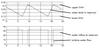
To verify the intended control solution and illustrate behaviour, an implementation was made in terms of a Simulink model. A reservoir model was added, and simulations were run according to different modes of operation – continuous level control, level control to within limits, and intermittent operation. Figure 4 shows a case of intermittent operation when inflow of water to the reservoir remains constant.
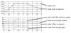
Figure 5 shows a case of level control to within limits, where an artificial step is disturbing the reservoir inflow. In fact, there is first a step up and then a step back down, and during this period the inflow is larger than the maximum flow through the turbine, so the bypass gate has to be opened as well in order to keep the water level at the limit.
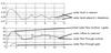
The continuous level control case (Figure 6) is applied when there is no reservoir or a very small one. Here, the inflow gets high enough for a short period of time to require opening of the bypass gate. The simulation model was also extended to allow simulation of start and stop of the turbine.
With a standardised integrated concept it is foreseen that significant cost savings and benefits can be achieved (Table 1).
TablesTable 1