Dealing with water inflows at Jinping
10 October 2008Construction of access tunnels A and B for the Jinping hydro power project in China was delayed for almost six months due to high pressure water inflows. Ziping Huang and Shiyong Wu present details of the water inflow problems with a focus on the characteristics of the flows, the impact on geological structures, and the change of strategy to cope with the flows. Given the difficulties encountered during excavation, the authors explain how the project is considered a great achievement in rock tunnelling
The Jinping access tunnels not only serve as the exploratory adit, test adit and construction adits to the headrace tunnels of Jinping II hydro power project, but are also important for traffic and transport access to both Jinping I and Jinping II hydro projects (Wu and Huang, 2008). Outward traffic from Jinping I and II, as well as the construction equipment and material being used on the Jinping II headrace tunnel and the Jinping I project, can pass through the 17.5km long access tunnels simultaneously, ensuring efficient transportation of external material and permanent facilities. The tunnels allow traffic to avoid 138kms of roads located in steep valleys and allow for more convenient communication between Jinping I and II projects to Guandi and other schemes along the upstream Yalong River. Early construction and pass-through of vehicles is important not only for the construction of Jinping but also for the continued development of the abundant hydraulic resources along the Yalong River valley (Norconsult Report No.1, 2004).
The access tunnels are characterized by long alignment, high overburden, high ground water pressure and complex geological conditions. Therefore, effective methods were needed to solve key technical problems such as large water inflow with high water pressure, high rock stresses leading to rock burst and squeezing, and possible adverse ground conditions in large fault zones. It was emphasised during the design stage, as well as in the contract documents, that proper excavation methods and treatment were essential factors for safe, economical and high-speed construction of the tunnels. Important features emphasised were forecasting and effective sealing of water (Norconsult Report No.3, 2004). The actual situation faced during excavation work show the great difficulties in implementing this approach and thus called for a combination of forecasting and water sealing techniques in advance of construction, with efficient drainage measures needed to deal with the large water inflows.
The access tunnels consist of two parallel tunnels spaced 35m apart. Tunnel A has a cross section of 30m2, with tunnel B measuring 35m2. Work on the tunnels started in October 2003, with breakthrough planned for the end of 2007. Actual breakthrough of Tunnel B occurred on 16 May 2008, with breakthrough of Tunnel A achieved on 8 August 2008. Large water inflows were the main reason for the delay in excavation. This paper presents a case study of the water inflows and investigates the features of water bearing structures that contributed to the water in-burst to the tunnels. The conclusions can be used as a guide to forecasting, treatment and drainage of water inflows in similar geological conditions.
Geological conditions and water-bearing structures
Geological conditions
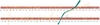
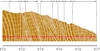
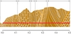
The rocks along the Jinping access tunnels belong to the Triassic period. They are mostly composed of carbonate rocks and slates, metamorphosed sandstone and a small part of green schist. The carbonate rocks occupy 16.23km of the 17.5km tunnels. The intact rocks have saturated (wet) uniaxial compressive strength sc = 60 - 95 MPa. All rocks, except for schists (and mudstone) are brittle. Ninety six percent of rock masses belong to Class II and Class III according to the Chinese Rock Mass Classfication System (Ren, et al. 2001). The rocks mainly dip eastwards in the eastern part and towards the west in the western part with strike generally N-S to NNE-SSW. They will therefore intersect the Jinping access tunnels mostly at a right angle. Figure 1 shows sections along the tunnels between Jinping I and II hydro power stations. During excavation 187 faults were encountered in the twin test edits with maximum thickness ranging from 1.7m to 5m. Tensile faults with strike NWW~NEE dominate. There are approximately six joint sets observed, mainly tight. Joints along bedding/foliation planes in limestone/marble often show an open nature. Most faults and joint sets generally have the same orientation; joint sets 1 and 2 plus fault F8 cross the access tunnels at an oblique angle, the rest mainly lie across the tunnels. The folds developed tightly, and mainly strike SN (Figures 2 and 3). The NNE oriented structures are featured as a type of extrusion while the NWW oriented tension and torsion. These structures form the groundwater network dominated by vertical direction (Ren, et al. 2004). During the preinvestigations, it was found that the groups in which karst has been most developed are the Baishan (T2b) and the Zagunao (T2z) groups. They occur along more than 10km of the tunnel.
Two twin adits have been excavated, 3948m (PD1) and 4168m (PD2) long at Dashuigou, 200m lower than the east side of access tunnels where the Jinping II power station is planned. Numerous tests have been conducted in the adits, such as rock stress measurements, grouting tests, and water pressure tests etc. All relevant information and measurements were applied in the evaluations for layout, design and rock engineering.
Groundwater and the water-bearing structures
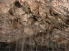
The steep topography with more than 1500m overburden for 73% of the Jinping access tunnels results in very high water pressures at the tunnel level. As described earlier, a major part of the Jinping tunnels are located in marble/limestone occurring in various mixtures, ranging from pure marble/limestone via brecciated marble to argillaceous limestone. Karst features can develop in such rocks. Karst is a result of the dissolving effect of water from circulation of water along discontinuities (joints, fissures, shears and faults etc) (Figure 4). Over time the process can form openings in the rocks ranging from small fissures through to large caves. The aperture of the joints will vary with the rocks and the stress conditions. The degree of karstification in the carbonate rocks can be divided into:
• Very small millimetre sized opening(s) along fissures or joints from initial karst activity.
• Small channels of centimetre size.
• Moderate openings (cavities) of decimetre thickness.
• Development of large caves of metre size.
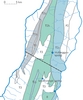
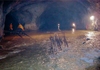
Thus, there are possibilities of encountering water-bearing zones in the carbonate rocks. With the high groundwater pressures, the potential water inflows may be large and high pressured. Such occurrences could lead to excavation problems, time delays and high extra costs. The twin adits (PD1 and PD2) had five inflows larger than 0.1m3/sec, with maximum of 4.91m3/sec. The outer ones dried out, but the inner ones experienced constant large inflows over several years. After being plugged, the maximum water pressure in the plugged part of the adit has been measured at 10.2 MPa. There are two main springs in the eastern area at el. 2130-2174m (Figure 5) where the changes in outflow were found, showing that the combination of faults and karst can develop huge underground water systems.
Based on the thorough pre-investigation and study, it is unlikely that a large continuous karst cave system exists at the level of the access tunnels. It is more likely that groundwater occurs under the following circumstances:
• a) Intersection between different rocks, especially where the tunnel moves from soft rock mass to hard and soluble rock mass.
• b) Development of folding, where the tunnel crosses larger folds, especially a syncline.
• c) EW and NNE striking discontinuities (faults or large joints).
• d) Intersection between discontinuities striking EW and some rock layers.
Planned water treatment strategy
Based on the geological conditions and concern about karst development – particularly from experiences gained on projects outside China – the planned water treatment strategy was to detect possible large water inflows ahead of the tunnel work to avoid accidents, delays and extra project costs, in addition to ensuring safe tunnel construction. Pre-grouting was to be carried out before excavation through the water bearing zone.
Forecasting water inflow
The forecasting methods to detect water-bearing structures include geological forecasts, geophysical methods and drill holes. The geological method makes use of geological information gained from field investigations and during construction. Therefore, it is important that the geologists closely follow the excavation and the results of other forecasting methods used. The geophysical methods make use of the propagation, reflection and/or refraction of waves in the rock masses, including Tunnel Seismic Prediction (TSP) for long distances from 50m to 100m and 1-2 hours testing period, Ground Penetrating Radar (GPR) for distances of 0 to 20m ahead of the tunnel face, and Ground Sonar (GS). Probe holes 5-50m long (typically 30m) were planned ahead of the tunnel face, to be made by the drilling jumbos used for blast holes. Modern computerized jumbos can record features such as drill speed, thrust, penetration, and amount of water supply. The results can be combined with geology in a forecast of water-bearing structures and their positions. As the drilling jumbo can easily be used, no additional equipment is necessary (Norconsult Report No.3, 2004).
Pre-grouting
Post-grouting – or sealing of flowing water – in larger quantities and pressurized water is very difficult. It is a very time-consuming method, especially if the water enters the tunnel from several joints or openings. Therefore, it was suggested that water sealing be carried out before the tunnel is blasted into the water channels – the pre-grouting method. This method reduces the risk of flowing ground (mixture of water and mud) into the tunnel, which could prove dangerous to workers.
Norwegian experience over the past 30 years of sealing water inflows in different types of tunnels has shown that the combination of medium long probe holes and pre-grouting are a good solution for both time consumption and cost. To carry out this approach, grouting equipment, experienced advisers, and a trained crew were required to select the right grout mix with additives (Norconsult Report, No. 3, 2004).
Emergency treatment of large quantities of inflowing water had also been planned.
Case study of large water inflow
In its largest amount, 7m3/sec flowed into the two east side tunnels with judged maximum water pressure of 4~5MPa (may even be higher) and 3.4m3/sec with maximum water pressure of 6~7MPa flowed into the west side tunnels. After grouting, the inflow reduced to 1.4m3/sec in the west side tunnels. In the east side, total inflows of about 7m3/sec did not change during the excavation. Part of Tunnel A is used as a drainage tunnel.
Inflow into the west side of the tunnels
A summary of water inflow greater than 20l/sec in the west side of the access tunnels is given in Table 1 and Table 2 for Tunnel A and Tunnel B, respectively. Significant inflows are marked in bold. As shown, there are large inflows in two sections in Tunnel A and four sections in Tunnel B. Descriptions of the inflows are given briefly in the notes. Figures 6-7 show the inflows in the west side tunnels. In locations with large water inflow the initial inflow represents the maximum amount. Since the inflow reduced with time in most cases, the total steady inflow is much less than the sum of the initial inflow. Water inflows after post grouting are listed as well. There are still three locations with initial inflows greater than 1m3/sec [AK5+150+230,1.6m3/sec, BK1+ 140,7m3/sec, BK2+635,15.6m3/sec].
Inflow into the east side of the tunnels
Inflow at BK14+888
The first significant high-pressure water inflows were encountered in the east side of Tunnel B, at Station BK14+888 on 8 January 2005. It was near the roof at 3.2m depth in a blasting hole. The water in-burst had an estimated inflow of 200l/sec and an assumed pressure of 4.7MPa. The water jetted out 18m and negatively influenced work conditions about 50m from the face. The contractor had used Ground Penetrating Radar (GPR) to forecast ground water. This showed that in the section BK14+460 to BK14+445 the rock is not uniform, with electromagnetic wave with high speed, suggesting ground water probably existed. TSP had also been used, but gave no evidence of water. Probe drilling ahead of the tunnel with six holes 5m long in the contour along the walls (with no overlap) had been performed over this section. According to the Contractor, they did not detect any water under (high) pressure. Some water had occurred in the blast holes, but it was not until drilling of the blast holes in the upper part of the face that the water in-burst took place. The inflow measured 164l/sec in the funnel pipe. This remained the same to 30 March 2005, when there was another inflow at AK14+756 in Tunnel. It was almost a year before further excavation could be carried out (Norconsult Report No. 5, 2005).
According to the geological observations, there is a fractured tensile zone oriented N70°W, NE 65°, opening up to 10cm, in T2y5 rock, i.e. dark/grey limestone and marble. The water seems to be supplied from this structure. In several locations in the left and right side walls in the vicinity, there are tensile torque joints close to EW, which are nearly vertical. There are karstified fissures and small cavities along the fault or tensile joint planes. The karst development most likely formed local channels where the calcite rock has dissolved. The channels may form a complex network along the fault or joint plane.
Inflow at AK14+762
On 30 March 2005, 10 minutes after blasting, water burst into Tunnel A at Station AK14+762 in the lower part of the left side wall, near the tunnel face. Water comes from a karst channel. The high pressure water in-burst forms a cavity 1.2m wide, 2.8m high and 4.2m long. The maximum inflow was measured at 6.7m3/sec. The water bearing structure is controlled by two sets of tensile fractured zones oriented N65°E, NW82° and N70°W, NE64°, in rock T2y5. The water inflow is constant and more than 2m3/sec (Wu et al. 2007).
Inflow at AK13+878
On 15 March 2006, water burst into Tunnel A at Station AK13+878, jetted out 10m, and measured about 2.2 to 2.7m3/sec. Water came from the bedding plane of N5°W, NE70°. Three days earlier, there was water inflow of about 15l/sec at Station AK13+892 from a bedding plane of N10°W, NE 65° in rock T2y6. The GPR test indicated a water bearing fractured zone strike N70~80°W. The fractured zone crosses the bedding plane, forming a water channel network. The inflow remains the same today.
Inflow at AK13+520 and AK13+494
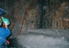
On 18 July 2006, gushing water of about 1.26m3/sec was encountered at AK13+520. The water inflow keeps constant, or even increases a little, as shown in Table 3. Figure 8 shows Norconsult experts visiting the site on 23 September 2006. The water bearing structure of a fractured zone has orientation of about NWW.
When preparing blasting holes at AK13+494 on 26 January 2007, a large amount of water (about 2.8m3/sec) gushed into Tunnel A. The water bearing structure is oriented N80°~85°W, NE 82° in rock T2y5. The inflow reduced but remains constant to today.
Characteristics of the large water inflow
Significant water in-bursts listed in Tables 1 and 2 in the west side of the access tunnels, and the large inflows, are summarized in Table 3 (faults name updated). It indicates that the water bearing structures are faults and fractured zones. The observations of inflows indicated karst denudation fissures, karst opening and karst cavities have developed along faults and fractured zones. This verified the conclusions reached in the pre-investigation and study. It is unlikely that a large continuous karst cave system exists at the level of the access tunnels. It is most likely that ground water occurs where the tunnels encounter discontinuities of faults, large joints, large folds, and intersections between rocks.
There is a discrepancy on the change of the inflow with time comparing inflows in T2z rock group with those in T2b and T2y rock groups. In T2z rock of Zagulao group, the very large amount of water which burst into the tunnel at AK1+177, BK1+130 and AK2+637 reduced rapidly and vanished in a short time. This means that the water bearing zones are large but are not connected to continuous water supply resources. The formations of three rock group are also different. In the Zagulao group, there are other types of rocks rather than carbonate rocks, such as slates, metamorphosed sandstone and a small part of green schist that are not soluable and thus probably isolate the water bearing zones to a certain extent. T2b rock of Baishan group and T2y rock of Yantang group are pure carbonate rock. The water bearing structures consist of networks of fractured zones and karst channels that have good connections to water supply resources towards the southern region, meaning there were continuous water inflows once the excavation encountered such a network.
There are approximately two sets of faults or fractured zones with strikes close to SN and NEE~NWW, dip angles mostly from 70° to 88°. The NEE~NWW oriented faults or fractured zones with majority of tensile faults contributed the major percentage of the large water inflows. The faults are classified as Class II and Class III according to the Chinese Classification System on Geological Structural Planes. These faults normally extend from tens of meters to hundreds of meters with widths less then 1m for Class III and more than 1m for Class II.
Discussion
The completion of the excavation provided opportunities to review and verify the design and construction of the tunnel with regard to the water inflow. The characteristics of water bearing structures determine the way to cope with the water inflow. In forecasting water inflows, identification of faults or fractured zones is extremely important. The probability is higher for a planar structure to be detected than for a karst channel or a karst channel network. Therefore, it is possible to implement the forecasting methods more efficiently than was generally done, even though there were some water inflows from karst cavities or channels that were extremely difficult to detect.
On the other hand, it is not certain that the pregrouting of the large amount of high pressure gushing water would be successful at all locations, even after the water was detected. Based on the actual forecasting and pregrouting carried out, the difficulties in treating water inflows should have been recognized in advance. Drainage should have been an essential consideration when tunnelling in such conditions. During the excavation, the preliminary approach of forecasting and pregrouting first, followed by drainage and excavation, was changed. The actual approach adapted during construction was that forecasting (using TSP and GPR, sometimes probe drilling) was carried out first to a certain extent to detect any large karst caverns, to allow excavation through the water bearing zone without any pregrouting, leaving any water encountered to be drained. This would then be sealed afterwards by post grouting. However, since there was no drainage channel or ditch large enough in the initial design in both tunnels, part of Tunnel A had to be used as drainage tunnel together with an excavated drainage shaft and the test adits. The fact that twin tunnels were designed meant that one tunnel could be made available for diversion of the underground water. However, this increased excavation time and meant greater efforts were needed to allow Tunnel A to function as a traffic route. This change of approach led to the construction of a drainage tunnel by TBM, which was planned to reach the three large inflows in the east side in September 2008 (as we go to press) for drainage of the Tunnel A and, potentially, the headrace tunnels. If the decision have been made earlier it would have allowed for more efficient drainage of Tunnel A.
Many large inflows are difficult to seal after they are revealed and the plan to reopen the access tunnel to traffic within the scheduled time is somewhat uncertain. To seal the largest water inflows at three locations in Tunnel A (No. 8, 9 and 10 in Table 3), an alternative is to construct weirs to keep out the water and reconstruct the drainage channel in Tunnel A to pass water out of the tunnel. These could be used in case the TBM built drainage tunnel could not excavate to the three large water inflow locations in time and may allow the access tunnels to be placed into service within the required time. Drainage is also of benefit to the construction of the headrace tunnels (Norconsult Report No. 7, 2008).
It is not only the features of the water bearing structures that can affect the treatment of the water inflow, the capacity of the contractors to implement the preliminary design approach to treat water inflow in advance can also affects the results.
Implementation of the planned approach by forecasting and pregrouting high pressure large water inflow requires the best in today’s drilling and grouting equipments, grout material and expertise, and decision making at site by experienced people when ground water with high pressure and potential large inflow is detected. At the end of 2004, drilling machines with air-leg feeders were changed to drill jumbo, however the old-fashioned grouting equipment did not change significantly throughout the excavation. These are not capable of treating the large pressure water inflow. An example was discussed at Norconsult Report No.3 in 2004. The works and time needed for sealing at AK1+117 in Tunnel A through a concrete plug with modern grouting equipment and experience as used in Norway is approximately three days. This is much shorter than the actual time it took.
It is important that experienced geologists and grouting experts make timely decisions at site when to stop excavation and start grouting, how to improve the probe drilling and geophysical forecasting methods, identify geological conditions and establish criteria based on water measurements from probe holes or blasting or rockbolt holes and geophysical prediction data (Norconsult Report No. 5, 2005).
Conclusions and recommendations
Breakthrough of the Jinping Access Tunnels A and B was achieved in May and August 2008. Even though excavation was delayed for almost half a year as a result of the large high pressure water inflows encountered, it is still a great achievement in rock tunnelling. A study of the water inflow during the tunnelling and related geological conditions indicates that the water bearing structures consist of a network of faults and fractured zones, along which karst fissures, channels or a few cavities developed. This highlighted the fact that it is important to identify the possible water bearing faults or fractured zones. The study also emphasised that planar faults or fractured zones are easier to detect than a karst channel or a channel network, indicating the need for forecasting and pregrouting large water inflows. However, given the high pressure and large amount of underground water at this project, and difficulties in both forecasting and pregrouting water inflow, it is unclear whether successful forecasting and pregrouting would be possible all the way along the tunnels within a reasonable time limit. Therefore it is also important to design a water drainage channel within the tunnels, or a separate drainage tunnel, for successful excavation of tunnels under such challenging hydrogeological conditions.
Ziping Huang, Ph.D, Norconsult AS, Sandvika, Norway, and Shiyong Wu, PH.D, Ertan Hydropower Development Co (EHDC), Chengdu, China
TablesTable 1 Table 2 Table 3