Designed to save time - Malborghetto hydro plant
18 September 2007Despite experiencing a lengthy permission process, construction work on the Malbor-ghetto hydro plant in Italy was completed well within schedule thanks to comprehensive planning and design work, writes Francesco Alessandrini and Claudio Frosio
The 4MW Malborghetto hydro plant is located in Italy, in upper Val Canale, in the Fella river basin. The project sits in the middle of the Giulie Alps, between the villages of Malborghetto and S. Leopoldo Laglesie, near the border between Italy, Austria and Slovenia. The area lies in the eastern part of the Alps chain which, obstructing the flux of wet air mass coming from the Adriatic sea and from Padana plain, causes the release of the main part of the steam contained in it. This fact is responsible for frequent rain with an average annual rainfall that varies from 1500 to more than 2000mm. Moreover the cold winter climate favours heavy snowfall and its gradual melting provides a steady and plentiful supply of water in spring.
The project's main characteristics are:
*Level of the intake: 694m asl
* Level of the discharge: 596.94m asl
* Head: 97.06m
* Penstock made of steel pipes, 1600mm diameter, with thickness variable from 12 to 14mm
* Penstock length: 6400m
* Maximum turbine flow: 5.00m3/sec
* Installed power: two 2MW capacity Francis turbines
* Estimated annual production: 18GWh per year
The lengthy permission process
The procedure for permission to build the scheme began in 1989 with the presentation of the first project, which was immediately opposed by the local community who judged it 'environmentally harmful' due to the presence of a regulation and settling basin inside the river area. The project was repeatedly modified until a design based on a bank intake with a weir as large as the riverbed (about 200m) and a regulation and storage basin of about 25,000m3 was chosen. Permission was finally granted for the diversion of water in March 1994.
However, further obstacles were encountered before the project could be built, with the authorities in charge of hydro and environment control requesting further modifications.
Between 1998 to 2000, more changes were made to the design, including dropping the regulation basin, before it went to the regional authorities in February 2000. These authorities however suggested an important variation to the course of the penstock which - instead of interfering with several road and river crossings and industrial areas - was moved along a disused railway, running alongside the river. This idea was endorsed by the Customer.
While these changes were being implemented, some serious flooding events occurred (notably in August 2003) which greatly modified the intake area, forcing changes to the structure. After defining the new project, the Regional Civil Protection - in order to ensure the passage of solid material which had caused serious damage during the last flood - objected to the weir being built as designed. Instead it wanted it transformed into a hydraulic fuse by means of a cofferdam which was removable during floods. It also required the intake to be lowered by 1m. The new plant design eventually obtained all the necessary permissions in September 2005.
The obstacles met while obtaining permission to build the plant were mainly as a result of the perceived environmental impact that had affected the plant since the initial project was presented, which incidentally coincided with the construction of a new motorway linking Italy and Austria that heavily modified the local landscape. This idea was reinforced by the fact that it was the first and only hydroelectric power plant to receive water from the Fella, which is a river of great local environmental importance.
In fact, the final design accepted by the local communities was the one which reduced the visible parts of the project as much as possible. This included a partial intake in the river-bed, a removable cofferdam, locating the basin partly underground and out of the river-bed, an underground penstock placed along a pre-existing railway, and a power station located almost entirely underground below the railway site and far from the village.
Realisation of the projectThe customer
In this particular case the customer is a skilful and experienced entrepreneur who, from the very start of the project, clearly stated the aims and priorities and was present at every step of the works. The customer kept a constructive attitude to the project, taking decisions at the right time and regularly meeting arrangements. This was decisive in quickly overcoming problems in the execution phase.
Time constraints
The working site is usually covered with snow with temperatures much below 0°C from mid November to mid April, while the period of low water suitable for project work runs from July to September. For this reason, the civil works had to be carried out from April to November; failing to do so would result in heavy costs as the project site would need to be shut down for six months before work could begin again.
Tender for civil works
The date fixed for execution of the civil works was 31 December 2005, to allow building work to start in April 2006. Expecting the project to be approved soon, chosen firms were invited to tender in February 2005 and, after inspections, explanations, integrations and modifications, two possible bidders were selected.
On 9 September 2005 authorisation for the project was approved by the regional office in charge, allowing the winning bidder to be chosen on 26 December 2005.
Tender for electromechanical supplies
Research among principal manufacturers had established that the necessary time for the supply and the commissioning of the electromechanical units was about a year. According to the schedule of works the machines could not be delivered before November, meaning the order had to be passed by 30 October 2005.
Tenders were called in May 2005. The offers, after inspections and requests for extensions, were made in September and negotiations went on for two months.
The order was in fact passed on 2 December 2005 with delivery within 11 months for the first group and one year for the second group.
Tender for construction of the penstock
A crucial issue in planning the orders was the choice of penstock pipe supplier. There were two options - award the winning civil works firm the contract for the supply and installation of the penstock, or order the penstock pipes directly.
Research among national and international producers revealed that the high demand for steel had created a situation of great instability in the market with a wild fluctuation in costs and shortage of available products.
In order to ensure timely delivery and cost effectiveness, the necessary steel coils had to be bought in advance and stored by the producer so that they could be used at the right time. This meant that a substantial economic advance was necessary for the purchase of raw materials. This was given directly to the pipes producer to buy the materials.
To ensure work schedules were met, it was decided that the building firm awarded the civil works contract would be given the responsibility for choosing the penstock pipes, controlling the production schedule and coordinating delivery of the pipes at a suitable time, while the Customer himself took charge of ordering and buying the pipes directly from the producer.
Time saving design
After assigning the orders for the electromechanical works, action was focussed on the design of the civil works. Because the works had to be carried out between April and November, it was necessary to design the works to avoid any possible problems - this included making adaptable choices and shorter working times.
For this reason the civil works were divided into two groups, the power station and intake, and the penstock.
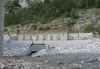
The power station and intake
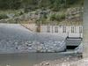
The structures were built from reinforced concrete and construction works easily met the strict schedule. The only restrictive issue when building the intake was that the work had to be carried out in a period of low water because it involved work on the riverbed. Works started in April 2006 on the power plant foundations, with the elevation works gradually following. At the beginning of November all works were completed and the turbines were ready for installation. In June, after executing the special foundations works, building work started on the intake and silter. This was completed by the beginning of December. Thanks to a comparatively dry season and an extended period of good weather only seven days were wasted because of heavy rain.
The penstock
Construction of the penstock represented the most crucial part of the building programme because of the potential problems that could be encountered. Particular issues that had to be considered included:
* For economic reasons three different thicknesses were used for the pipes: 12, 13, and 14mm.
* To follow the course with a broken line, and to fit the diversions allowed by the spherical joint, pipes with 17 different lengths had to be used.
* The course of the penstock meant that 15 streams or drains of different importance had to be crossed by overpass or underpass with siphons.
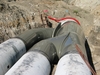
* The course crosses the Fella river on the old railway bridge and a restriction was placed that meant the pipe could not be higher than the existing parapet. The result was that the penstock had to be changed from the original selection of a 1600mm diameter pipe to three 900mm diameter pipes with upstream and downstream parts.
The small width of the available railway track did not allow the pipes to be placed along the track in advance, meaning one or more stockpiling areas had to be used outside of the track. The pipes were placed piece by piece as the installation was carried out.
The combination of three thicknesses with three different lengths, which included bends of different thickness and radius as well as the addition of special pieces for the man hole and air valve connections, meant a great number of pieces had to be used. As these could not be placed along the track, they had to be produced and delivered according to an precise schedule.
To solve the problem it was necessary to design the penstock to ensure the installation was easier and to reduce the choices to be made while working.
Penstock design
As the construction of the penstock was the most crucial work, in order to carry out the works in the allotted time it was necessary to face and solve all the problems during the planning phase, giving priority to prefabricated constructions which would be easy to install yet adaptable enough to face unpredictable events.
The first step was an accurate and detailed survey of the whole track. To make work easier it was decided to divide the track into four parts according to the service roads and stockpiling areas.
Considering the characteristics of the track, the spherical joint was chosen as means of pipe connection. It was proved in fact that by using the shift allowed by this kind of joint it was possible to complete most of the planned bends of the track without special pieces by simply making a broken line varying the length of the pipes.
The spherical joint allows a plano-altimetric regulation as well as an adequate fitting to real conditions and needs only outer welding, considerably reducing working time at the building site.
The track is characterized by several special works which are mainly plano-altimetric diversions of the track to pass under any obstacles. Detailed surveys and specific building designs were carried out wherever these works were necessary.
Also, the special works components, pipes or bends, were made with a spherical joint so that their installation, even in a bend or a siphon, would not be different from the installation in a straight line.
The end of the track was composed of 655 pieces of three different thicknesses and 17 different lengths. The abacus with the building characteristics of each piece and their position in the track was given to the pipe producer and building firm in March 2006.
Installation
The penstock track is naturally divided into two parts, upstream and downstream, from the Fella river crossing. Both of these are divided into two parts at a point where a special work is located. In particular the track was divided as follows:
* 1st part from the silter to the river Granuda, which is 2408m long.
* 2nd part from the river Granuda to the river Fella crossing, which is 1237m long.
* 3rd part from the Fella crossing to the tunnel, which is 1693m long.
* 4th part from the tunnel to the power station, which is 1051m long.
The main stockpiling area was near the former station of Santa Caterina, just upstream of the Fella crossing, with smaller areas along the track, where possible. Such areas were not used for storage because the delivered pipes were usually immediately installed, they were simply areas equipped for carrying the pieces from trucks to special vehicles within the site, with enough space for a minimum storage to allow delivery to carry on in the event that installation was delayed, or in turn to allow installation work to continue if delivery was delayed.
The installation work involved two independent teams and five welder teams. If delay was experienced, there was the option of employing a third team.
During the work a third team was actually commissioned, but not for the installation of the penstock but rather for breaking up the areas of rocky soil which were present, especially in the third and fourth parts of the track. This activity, carried out during the installation of the first and second sections, allowed a much quicker excavation during the installation and made the working time almost the same as the time of installation in loose soil.
The first pipe was delivered on 3 April 2006 and the installation began on 10 April from the second part starting upstream. The conditions met during the works were as predicted, without any particular unexpected issues and so, after about fifteen days, works also began the first part.
The first and second sections were hydraulically tested one by one, while the last two parts of penstock were tested together.
All the welds of the spherical joints were controlled by magnetoscope, while all the front welds were tested by X-ray.
The final hydraulic test was done on 28 June for the first part, 11 September for the sec-ond and 12 November for the last sections.
With completion of the connections to the turbines and by-pass valve, the filling began on 18 December, with the first turbine starting on 21 December 2006.
Conclusion
The permission procedure and construction work on the hydro plant at Malborghetto-San Leoplodo have proved how accurate planning is a necessary element to a successful project. During the approval procedure, planning was conceived in such a way as to reduce the environmental impact at the lowest level, finally meeting all the objections of the regional authorities. Moreover, during the execution phase, accurate and detailed planning, together with well-planned building works, proved successful in optimising the works and minimising construction times. Essential to the whole operation was a customer who performed his task in an excellent way, allowing the plant to be built in only eight months.
View of the intake at the project Intake View of the power station Station The Malborghetto power station Power station The Trifurcation to overpass the Fella river Trifurcation Picture of the schematic course Schematic Table 1 Table 2 Author Info:
Francesco Alessandrini is a civil designer and director of Alpe Progetti, an engineering company specialising in geotechnical and hydraulic infrastructure works.
Claudio Frosio is a mechanical engineer specialising in power stations, and board director of Studio Frosio, an engineering company involved in water resources and hydroelectric development.
TablesTable 1 Table 2