SMALL HYDRO
BENATKY NAD JIZEROU
Full health Czech
24 June 2004Refurbishment work in 2001 brought back to life an ailing small hydro power plant on the Czech Republic’s Jizera river, writes Martin Sintak and Jeanne Hilsinger
THE beginning of the twentieth century and the coming of the industrial age led to the development of thousands of small hydroelectric power plants in central Europe. But this development came to a virtual halt during World War II and the hiatus did not stop even when the war ended. Not only did the following 45 years not see any new development, but many existing plants were decommissioned and abandoned in favour of large scale power production.
Recently, a number of central European countries have begun to rehabilitate old sites and the number of small hydro plants is now increasing for the first time in over 60 years. While Poland, the Czech Republic, Slovakia, Germany and Poland have some legislation supporting renewable energy, more government aid is needed to accelerate the development of this source of energy.
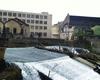
Benatky Nad Jizerou hydro plant
The story of a small hydro plant on the Czech Republic’s Jizera river, about 40km north of Prague, dates back to the sixteenth century. The first plant was built as part of a mill complex called Grosse Muhle Kremen – Benatek or ‘Big Lordly Mill’ in 1572. It was equipped with nine water wheels and stayed in operation for about 300 years.
Flooding of the Jizera river during the latter half of the nineteenth century and deterioration of the mill walls brought an end to the long life of the mill. A permit to build a new plant was issued at the end of the century and in 1892, a new modern hydroelectric plant with two Girard turbines produced by GANZ was commissioned in connection with the establishment of a factory for the production of synthetic carborundum production and grinding instruments and materials. The new company was known as Carborundum Electrite. These turbines were connected to long transmission shafts which powered the factory machines.
In 1918, the Girard turbines were replaced with two vertical Francis turbines, one large and one small; both with gear trains. The turbine shaft was connected to an iron cog gear with wooden teeth. A pinion gear then connected this to machines on the factory floor. Later, synchronous generators were installed and the turbines were able to generate electricity for general use.
In 1952, the weir was repaired and the weir body was covered by concrete plate over the original crib stone construction. Steel was inserted to some of the walls to provide extra durability. As small hydro was not a priority during these times, there was little or no maintenance and the plant again slipped into decline. The small Francis turbine was removed in 1976 and the large turbine in 1989.
Rehabilitation
In 2001, the Carborundum Electrite plant still existed and synthetic carborundum production continued. The company had recently received financing from a US venture capital firm. The site of the original Big Lordly Mill, however, had fallen into catastrophic conditions. The power house had been abandoned for many years and was filled with discarded machinery and other items. The weir and concrete structures were cracked in many places and further damaged by the severe flooding of the Jizera river during the summer of 2000.
A private investor purchased the site in 2000 and requested proposals for the rehabilitation of the site in order to maximise its potential energy production. The necessary rehabilitation included repair of the weir, the rehabilitation of all concrete structures for water handling, repair of the power house, new turbine housings and new mechanical, electrical and ancillary equipment. The site had a head of 4.2m and flow of about 24m3/sec.
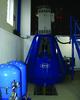
mavel, a.s., a Czech engineering and manufacturing firm specialising in turbines and related technology for small hydro power plants, developed a solution to maximise the power generated at the site while using as much of the original structures as possible. The solution was to increase the installed output from 560kW to 1MW in an environmentally sound way, with minimal new investment. The plan called for the use of most of the original concrete structures for water intake and exit. Two Kaplan turbines were installed and connected to asynchronous generators through a gear box. Due to the design of the original power house construction, one draft tube was indirect but designed not to lose efficiency. Finally, turbine bearings were cooled by water pumped up from new wells.
Hydro-Mechanical Equipment
The design process began with the selection of the hydro-mechanical equipment: turbine, generator and gearbox. The Mavel solution called for two vertical Kaplan turbines each with a runner diameter of 1.6m with gear box drives and asynchronous generator. Characteristics of each turbine-generator set are shown in Tables 1-3.
Weir/Other Structures
• Weir: Insurance received from the damage caused in the 2000 floods paid for extensive repairs to the weir and other concrete structures.
• Inlet System: Mavel designed the turbines to use the existing inlet system to channel the water into the turbine spirals.
• Turbine Spirals: The turbine spirals were built with a width of 2.6m and height of 5m into the original pit.
• Sluice Gates: The original wooden sluice gates were replaced with steel gates and mechanisms.
• Trash Racks: New trash racks were installed behind the sluice gates.
• Cleaning Machines: Two machines were installed into a reinforced concrete plate across the north side of the power house.
• Draft Tubes: Drafts tubes made of steel cone continue to steel elbows which grade from circular to rectangular and end with a concrete diffuser. The elbows for both are placed at the original base level of 182.35m above sea level (asl). The first draft tube was direct and follows the route of the original output water channel. The second draft tube is indirect and must move around the first draft tube. This draft tube was designed not to lose efficiency and both turbines maintain the same output. The end of the draft tube, however, required that the original concrete plate be demolished in order to create a lower level for the output at 180.65m asl.
Power house
The power house was completely renovated to accommodate the new hydro equipment. The new vertical Kaplan turbines were installed in the machine room and have a footprint of 8 x 14.5m. The cylindrical turbine casings are embedded in concrete which also creates the spiral ceiling and machine room floor at 188.6m asl. The turbines have four blades, a gear box, bearings and asynchronous generator. Ancillary equipment such as oil lubrication units, gear box cooling apparatus and hydraulics are also placed in the machine room.
Other Electrical Delivery
Mavel provided and installed the full electrical and control systems, including distributors and circuit breaker. Automated operation of the plant is achieved through the installation of the programmable system TECOMAT NS950. The control system allows the following operation: automated operation controlled by water level, manual operation or operation with an alarm.
A transformer station was built next to the south side of the power house. There is a dry transformer of 0.4/22kV with nominal output of 1250kVA and control room of 22kW in a classic cubic arrangement. The control room contains three cubicles; one each for switching for transformer, measurements and consumption/output.
The low voltage lead to the transformer is from the RP distributor by a cable which goes through the wall of the power house. The output into the supply network of 22kV STE is through a ground cable connection and along the river to the transmission tower.
Lubrication of Radial Guide Bearing
The radial guide bearings are cooled by water pumped up from a new well, filtered and delivered to the bearing. This water is then released into the river under the draft tubes.
Author Info:
Martin Sintak and Jeanne Hilsinger are with Mavel.
This paper was presented at the Hidroenergia 2004 conference, held in Falkenberg, Sweden from 17-19 June.
External weblinksMavelTablesTable 1 Table 2 Table 3 Table 4