Fuse plug construction to improve flood control
19 May 2006A fuse plug was constructed within an existing spillway at Douglas dam to provide 100-year flood protection within the city of Fort Collins, Colorado, US. Gregory G. Glunz and Gregg Batchelder Adams describe how the fuse plug will provide necessary flood detention without changing the normal operating conditions or requiring significant modifications to an existing spillway and dam
Modification of the previously existing emergency spillway structure at Douglas dam, located in the city of Fort Collins in Colorado, US, was completed as part of the Dry Creek Drainage Improvement project, a multi-dimensional flood control scheme for the city. Dry creek is a tributary of the Cache la Poudre river and encompasses an approximately 105km2 watershed. Development in the floodplain has essentially removed any downstream conveyance channels within the city of Fort Collins, and it is estimated that the 100-year frequency design rainfall-runoff event would result in approximately 1500 structures being flooded with an associated US$24M in damages.
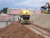
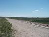
Douglas dam is an earthen embankment dam with a crest length of approximately 3700 feet (1128m), and a crest width ranging from approximately 20 to 35 feet (6 to 10m). The dam is approximately 39 feet (11.89m) in height at the maximum section. The previously existing emergency spillway is a trapezoidal section, with a 642 foot (195.7m) bottom width, 5H:1V side slopes, and 7.5 foot (2.2m) height. The spillway crest control structure includes a concrete cutoff wall that extends to bedrock. The spillway was designed to safely pass 75% of the Probable Maximum Precipitation (PMP) or 1125m3/sec, as required by the Colorado State Engineers Office (SEO). Figure 1 shows the emergency spillway prior to construction of the fuse plug.
The State of Colorado does not have specific published design criteria for fuse plug spillways. Therefore, the SEO was contacted for guidance in establishing the design criteria. The design criteria that were recommended by the SEO include:
• It is preferred that the peak discharge from the operation of the fuse plug not be greater than the peak inflow to the reservoir at any time.
• If criteria No. 1 cannot be met, an Incremental Damage Assessment (IDA) can be performed, following SEO criteria, to demonstrate that there are no significant incremental damages from operation of the fuse plug structure.
• The fuse plug structure should be designed following US Bureau of Reclamation (USBR) guidelines (Pugh, 1985).
In order to meet discharge criteria, the fuse plug will need to be divided into multiple segments to provide a staged release of stored water. The staged release of water will be accomplished by constructing the fuse plug segments to different elevations. Additionally, the length of the fuse plug segments will vary. Generally, the fuse plug segments that are lower in height will be shorter in length. The selection of the number and size of fuse plug segments is briefly discussed in the following sections.
Hydrologic and hydraulic design considerations
Hydrologic and hydraulic analyses were completed to evaluate the impacts associated with the operation of the fuse plug for various storm events and potential performance scenarios. The various performance scenarios considered possible variations in lateral erosion rates and breach formation times, as well as the potential for multiple fuse plug segments operating simultaneously. Reservoir routing analyses were completed using a spreadsheet developed to simulate the various fuse plug scenarios. The first analyses evaluated the length and height of individual fuse plug sections to determine if the first SEO criteria could be met. It was determined that a fuse plug with 13 individual segments, each with different pilot channel elevations, would be required in order to limit the peak fuse plug outflow to less than the peak reservoir inflow at all times.
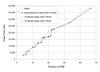
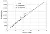
A fuse plug with 13 segments was not considered to be a practical option because of the limited height available in the existing spillway. Therefore, an IDA was conducted for numerous percentages of the PMF to demonstrate that fewer fuse plug segments could be used. From the IDA and the additional analyses discussed later in this paper, it was determined that the optimum number of fuse plugs segments would be six. Figure 2 shows a comparison between the 13-segment fuse plug peak outflows, the six segment fuse plug peak outflow and peak reservoir inflow.
The six-segment fuse plug spans the entire width of the existing emergency spillway, except for a 30 foot wide opening at the centre of the spillway. The 30 foot (9.1m) opening is used to restrict the outflow from the more frequent storm events by reducing the effective crest length from the previous 642 foot (195.7m) width. Each fuse plug segment is a zoned earth and aggregate embankment structure that is designed to erode to a concrete slab level when the reservoir water surface elevation reaches a pre-determined level.
The height of the first fuse plug pilot channel will be set 4 feet (1.2m) above the existing spillway crest, the second 0.5 feet (0.152m) higher, and the remaining four segments will increase in elevation at 0.25 foot (0.076m) increments. The initial 4 foot (1.2m) high fuse plug was selected to provide the necessary flood storage volume. The incremental height between the individual fuse plug sections was selected in an attempt to minimise the impacts of the fuse plug operation while maintaining the maximum fuse plug section at least 1 foot/0.3m (pilot channel 2 feet/0.6m) below the dam crest. The small difference in the fuse plug heights could lead to the potential for multiple sections to operate at the same time. The impacts from this scenario are discussed later.
Incremental damage assessment
Hydraulic modelling for the IDA was completed using HEC-RAS version 3.1.1 in conjunction with HEC-GeoRAS. The incremental damage assessment methodology, provided by the Colorado SEO, states that the IDA should be performed based upon a comparison of two flooding events: 1) the non-event scenario and 2) the flooding event that just causes the specified event to occur.
A comparison should be made between the resultant two floods, such that no additional loss of life or ‘significant’ incremental damage is expected. This comparison is made using two criteria: 1) the incremental increase in depth of flow and 2) the product of the incremental depth and average cross-section flow velocity. If the results show that the incremental depth is less than two feet (0.6m) and the product of the incremental depth and average velocity is less than seven feet (2.1m), then the event is considered to not result in significant incremental damages. Cross-sections for the hydraulic model were located at critical structures and other areas of concern. The results showed that a six-segmented fuse plug meets the IDA requirements of the SEO.
Effects of lateral erosion rate
Initial estimates for the lateral erosion rate of the fuse plug embankment were estimated using the model study information from Pugh (1985). Based on the fuse plug geometry, a lateral erosion rate of 1 foot/min (0.3m/min) or faster in one direction could be expected. A sensitivity analysis of the lateral erosion rate was conducted to evaluate the potential impacts of the fuse plug eroding faster or slower than expected. The location of the pilot channel can either produce erosion in one or two directions depending on its location relative to the divider walls.
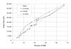
The lateral erosion rates considered were 0.5 (0.152m), 2 (0.6m), 4 (1.2m) and 10 feet (3m) per minute. Results from the analyses are presented in Figure 3. This figure indicates that for lateral erosion rates slower than 2 feet/min (0.6m/min), the difference in peak discharges for fuse plug operating conditions could result in increases in the incremental depths, and in the products of the incremental depth and velocity.
Lateral erosion rates slower than 2 feet (0.6m) per minute result in more fuse plug segments operating than is necessary if the sections erode faster. However, there are only minimal changes in the discharges for erosion rates faster than 2 feet (0.6m) per minute. To achieve a 2 feet (0.6m) per minute or faster erosion rate and reduce the potential for simultaneous operation of fuse plug segments, the pilot channels were placed in the middle of each segment to provide an assumed 1 foot (0.3m) per minute lateral erosion rate in two directions, thus minimising the potential for the fuse plug to erode to slowly.
Effects of delayed breach initiation
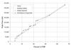
A sensitivity analysis for the fuse plug was performed for various lateral erosion rates while delaying the time to initiate the breach by 15 minutes. The sensitivity analysis described in the previous section assumed that the breach formed instantaneously when the water surface exceeded the crest of the pilot channel. Figure 4 shows a comparison between the instantaneous breach development used in Figure 3 and the 15-minute delayed breach initiation with 2 (0.6m) and 4 feet (1.2m) per minute lateral erosion rates. Results for the delayed breach analysis indicate that lateral erosion rates of 2 feet per minute or slower result in more fuse plug segments operating than necessary. This analysis confirms that the lateral erosion rate needs to be 2 feet (0.6m) per minute or faster.
Multiple segments operating
The modelling of two fuse plug segments operating at the same time was also conducted because of the potential for the inflow hydrograph to be different from the modelled hydrograph. This analysis could also be used to represent the potential for the breach times to be significantly different between two fuse plug segments, one delayed and one instantaneous. This scenario, although highly unlikely, assumes that the first segment does not begin to breach until water enters the second fuse plug’s pilot channel and the second fuse plug breaches instantaneously.
Results from the fuse plug analysis, presented in Figure 5, show that for a lateral erosion rate of 2 feet (0.6m) per minute, the simultaneous operation of the first two segments results in an increase in peak discharge when compared to the single segment operation scenario. This increase in peak discharge occurs for limited events up to approximately 20% of the PMF. These increases could result in incremental damages, however additional analyses for incremental damages were not conducted because the situation was considered highly unlikely and the incremental increase in discharges was not large.
Geotechnical design considerations
The fuse plug cross section was developed following the guidelines set forth by Clifford A. Pugh in the paper titled, ‘Hydraulic Model Studies of Fuse Plug Embankments,’ dated December 1985. Pugh and his colleagues at USBR developed a prototype cross section for fuse plugs ranging in height from 10 to 30 feet (3-9m). Through model testing they were able to identify key design features that affected the lateral rate of erosion for the fuse plug. A few of the features included sloping of the clay core to prevent shielding of the downstream materials, which could delay erosion, and the incorporation of sand filters on the upstream and downstream sides of the clay core to prevent saturation of the downstream zones, which in turn could prolong the breaching process. From the results of the model tests, fuse plug geometries were developed based on the height of fuse plug desired and the lateral erosion rate required. Additionally, prototype cross-sections and material gradations were developed that could be used to achieve the desired lateral rate of erosion.
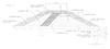
This project’s fuse plug cross-section was designed in general accordance with the guidelines specified by Pugh. However, the height of the tallest fuse plug measures only 6.5 feet (1.98m) to the crest and the model testing was developed for prototype fuse plugs ranging in height from 10 to 30 feet (3-9m). This project’s fuse plug does not fall in this range; some of the guidelines would produce a fuse plug geometry that is not practical to construct. As a compromise between the design criteria and constructability, the recommended sand filters and the zones of compacted sand and gravel on the upstream and downstream sides of the clay core were combined into single zones of concrete sand. The typical cross-section for the final fuse plug geometry is shown in Figure 6.
The fuse plug segments are separated by six concrete divider walls that extend from the existing concrete spillway crest to the top of each fuse plug segment. The divider walls were constructed with a battered slope of approximately 1H:8V to enable better compaction of backfill material. Due to better compaction at this interface, battered walls typically reduce the potential for seepage along the wall, and therefore reduce the potential for premature operation of the fuse plug segments.
The divider walls, clay core and downstream fuse plug zones were placed on a new concrete slab that was attached to the existing concrete cutoff wall. The existing concrete cutoff wall extends down to bedrock. The concrete slab prevents the seepage of water into the downstream zones of the fuse plug and provides additional stability for the cutoff wall in the event that severe erosion occurs in the spillway channel.
Slope stability, sliding stability, and filter compatibility evaluations were completed as part of the design. The slope stability analysis considered circular and non-circular shear surfaces under steady state and rapid drawdown conditions. A sliding stability analysis was performed to evaluate the potential for sliding failure as a result of impounding water behind the fuse plug. Filter compatibility evaluations were performed to evaluate the potential for piping of materials through the fuse plug and to specify material gradations to prevent piping.
Fuse plug test section
Prior to completing the final design and preparing the specifications, a fuse plug test section was constructed to aid in developing the construction methodology and Quality Control procedures. A representative of the Colorado State Engineer’s Office observed the test section and provided comments regarding the construction. During the test section a trench was excavated through the upstream zones and clay core to inspect the in-situ material and the interfaces between the various zones. The test section demonstrated that the proposed construction methodology would generally meet the design intent.
The test section was 30 feet (9.1m) long and had the same dimensions as the largest fuse plug section, 6.5 feet (1.98m) high. The moisture and density requirements for placement of the clay, sand and aggregates were similar to those for a typical earthfill embankment. The sand was wetted and placed in 8 inch (20.3cm) lifts using a smooth plate vibratory compactor. Compaction of the clay core was completed using jumping jack type compactors in conjunction with a vibratory trench compactor with sheeps foot rollers. The clay material was placed slightly wet of optimum to provide better compaction and sealing against the walls and slab. Figure 7 shows the clay core material being placed with the trench compactor. Both sand zones and the clay core were overbuilt and then cut back to the proper lines and grades using a front-end loader. The process of over building the smaller (thinner) zones provided a uniform placement of material throughout the cross-section.
Conclusions
The design and construction of a fuse plug spillway for flood control is a multi-faceted process that requires significant investigation and analysis. The use of the fuse plug for this project was not selected until the potential hazards for the existing dam and the areas downstream of the dam were identified and evaluated. Identifying the various potential operational scenarios was critical in defining the potential hazards. Minimising the impacts associated with the fuse plug operation can be accomplished by dividing the fuse plug into multiple segments with varying pilot channel elevations.
A relatively small fuse plug cross-section can be constructed using typical earthfill dam criteria. Some zones from the USBR design guidelines were combined to improve the constructability of the fuse plug segments. Overbuilding of small (thin) fuse plug zones improves the overall quality of the structure.
Author Info:
Gregory G. Glunz, P.E., Water Resources Engineer, and Gregg Batchelder Adams, P.E., Senior Geotechnical Engineer, URS Corporation, 8181 East Tufts Avenue, Denver, Colorado 80237, US. Tel +1 (303) 694-2770. Fax +1 (303) 694-3946. Email: greg_glunz @urscorp.com, gregg_batchelder_adams@urscorp.com.