Lessons from the past
5 November 2008Kenneth D Hansen provides an insight into what today’s engineers can learn from the first five years of RCC dam construction in the US
The birth of the roller compacted concrete (RCC) dam has been called ‘the single most important development in dam engineering in the past quarter century’. RCC dams gained acceptance worldwide in a relatively short time due to their low cost, which is derived in part from their rapid method of construction. By the end of 2008, the number of RCC dams completed in the US more than 15m high totaled 46. Worldwide, the number is very close to 400.
During the first five years of RCC development in the US, eight dams were completed. A lot was learned from their performance – both good and not so good. Some of the problems encountered with respect to seepage, durability and cracking were well publicized. In this way, designers of future RCC dams could learn from the past.
It is always easy to have 20-20 hindsight. A lot of credit must be given to the designers of these initial RCC dams. They were really pioneers in dam building. These pioneers ‘stuck their necks out’ in the development of this new method of building a safe concrete dam quicker and at less cost. The early designers got 90 to 95% of the entire process correct and should be applauded for what turned out positively, not the results that were less than anticipated.
During the five year period from 1983-1987, eight new RCC dams were completed in the US. The names and location of these dams is shown in Table 1. If we were to categorise these dams by cementitious content (Portland cement [C] + fly ash [FA] ), the first seven dams might be referred to as lean mix RCC dams in that they contained less than 110 kg C+FA per m3. Upper Stillwater Dam is a high-cementitious (or high paste) RCC dam as it contained more than 160 kg C+FA per m3. The lean RCC dams were also constructed using a drier consistency RCC mixture.
Discussion of the relevant features and lessons learned from each dam follows.
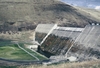
Willow Creek Dam – Oregon
RCC for a new dam in the US began in 1982 with construction of this flood control dam just upstream of the Town of Heppner, Oregon.
The ‘all RCC dam’ containing 331,000m3 was placed in just five months, at an average in place cost of about $25.00 per m3. This proved that an RCC dam could be built faster and at considerably less cost than a comparable concrete gravity or earthfill dam.
Although no transverse joints were included in the long dam, no problems with cracking were reported. However, seepage through the dam raised concerns with the US Army Corps of Engineers (USACE).
Soon after the reservoir was filled in the spring of 1983, seepage in the drainage gallery and at the downstream face was noticeable. As with nearly all RCC dams, measured seepage reduced with time. This reduction is seepage is attributed to additional calcification of the RCC mass, silting, and other materials filling voids in the RCC.
USACE decided to reduce seepage by grouting. Its initial trial using chemical grouting from the dam’s upstream face did not produce sufficient reduced seepage. Subsequently, a cement grouting programme reportedly reduced seepage significantly. Further reduction of seepage was measured during the next two years. Still, 15 years after construction, a line of seepage continues to be visible on the downstream face with bushes growing out of the wet loose RCC.
With the joints between the upstream precast concrete panels unsealed, the RCC mass was considered to be the primary water barrier. The initial seepage through the dam was attributed to voids at the lift lines caused by segregation of the three-inch maximum size coarse aggregate of the lean-dry RCC mix during construction.
The main lesson learned from Willow Creek was that a more impermeable upstream face was needed for seepage reduction, and secondly that a reduction in the maximum size aggregate would help reduce segregation of the lean, dry RCC mixture during placement.
Winchester Dam – Kentucky (now named Carroll E. Ecton Dam)
The design for this small municipal water supply dam was similar to Willow Creek Dam in that precast concrete panels were used as stay-in-place forms for the vertical upstream face. However, there was one major difference that led to improved seepage performance through the RCC dam. A 65 mil thick PVC membrane was attached to the downstream side of the panels during casting. Then, following installation, both the horizontal and vertical joints were heat-welded together with the use of a strip of the membrane material. Conventional concrete was then placed between the panel and the RCC as a precaution against damage to the membrane during RCC placement and compaction.
This improved upstream facing system effectively stopped any measured or noticeable seepage through the dam after filling in 1985. However, leakage under the dam through the jointed limestone foundation was considered excessive. It was remediated by a cement grouting program.
At Winchester, the main lesson learned was that membrane faced panels proved to be an effective upstream facing system for an RCC dam. Also, as with any dam, seepage through the foundation or abutments needs to be considered and controlled.
Middle Fork Dam – Colorado
This RCC dam was constructed in 1984 to provide a supplemental water supply and flood protection for a proposed, but never built, shale oil mine and processing plant. The dam has an upstream and stepped downstream facing of conventional concrete, but no transverse joints at its narrow canyon site.
As with many RCC dams, the concrete face effectively reduced seepage through the dam to acceptable limits. Calcification of the RCC mass further reduced seepage with time, with the seepage reduction being the most rapid during the first three months after complete reservoir filling in the fall of 1984.
Significant development of calcite (calcium carbonate) formed when calcium hydroxide from the cement hydration process is carried by seepage water to the gallery or dam drain holes. Here, the calcium hydroxide combines with carbon dioxide from the air to form this hard white precipitate. With time, this material can cause drain holes within the dam to clog. The drain holes at Middle Fork Dam were re-drilled in 2007 to reestablish their effectiveness for capturing seepage water and assuring reduction in uplift pressures.
Galesville Dam – Oregon
Galesville Dam is another example of the rapid placement of RCC. The 161,000m3 of RCC was placed in about 1.5 months in basically June and the first half of July in 1985. Placing all conduits through the dam in a concrete encasement on one abutment helped speed construction. The vertical upstream face is conventional concrete with no transverse contraction joints. Unformed RCC was used for the downstream slope with overbuild allowed by the contractor. The overbuild was allowed to ravel and served as a sacrificial layer of poorly compacted RCC.
For seepage control, two 20-mil thick layers of a coal-tar based elastomeric membrane was sprayed on the upstream face. A delay in the start of the RCC placement to warmer weather helped contribute to the initial formation of seven thermal related cracks that continued through the entire gravity structure. Following completion of the dam, unusually cold weather hit the site causing a reduction in volume and thus cracking. The sprayed on membrane did not have sufficient elasticity to bridge the cracks.
Repair methods used to reduce seepage through the cracks included: (1) dumping pelletized bentonite from a boat near the widest crack; and (2) divers caulking the cracks to a depth of 50 to 60 ft (15-18m) below the water surface. The dumped pellets worked reasonably well when there was sufficient velocity to draw the bentonite into the crack. Cracks lower in the structure remained uncaulked due to a limitation on the depth the divers could effectively work. The repair methods, together with some natural calcification and siltation, reduced seepage by about 70% over a two year period.
Grindstone Canyon Dam – New Mexico
The seepage control system for this 432m long RCC dam consisted of a conventional concrete face and partially sealed face joints spaced 4.6m on center. No waterstopped transverse joints were included in the design. It was reported that the original joint sealant used in the vertical dummy joints was not of the type recommended by the manufacturer for underwater placement and was not applied to the depth specified in the formed V-notch joint.
Upon initial filling in 1988, nearly two years after completion of the dam, seepage exceeded the measuring capacity of the flume in the channel downstream of the dam. Calcification and siltation, together with repair of one hole at the right-end of the gallery, helped reduce total seepage. During cold weather the following winter, the RCC mass contracted and measured seepage increased. The reservoir was then lowered to allow for repair of the vertical joints and cracks. In addition to the seepage through cracks and joints, the author feels that additional seepage may be coming through horizontal lift lines in the conventional concrete face due to a delay in placing successive layers of facing concrete.
In 1995-1996, the New Mexico State Engineer’s office reported it oversaw another rehabilitation project that reduced seepage by 70%.
Monksville Dam – New Jersey
Monksville Dam became the first RCC dam constructed in the eastern US when completed in 1986. It had a conventional concrete face upstream and uncompacted RCC on a 0.78H:1.0 V downstream slope. It was the first dam in the US to utilise a thermal analysis for the purpose of determining among other things the spacing of waterstopped transverse joints. Because a delay in RCC construction due to warmer weather would produce higher placing and peak temperatures, the designers decided to decrease the spacing of waterstopped joints at higher elevations. The seepage control system, which included placement of bedding mortar on every other lift near the upstream face, worked reasonably well.
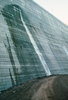
It was on the exposed RCC downstream face that things did not work out as well as expected. The original design called for a higher cement content (110kg/m3) RCC mix along the downstream face. This zone was not placed as intended. It was believed that the lean RCC mix (64 kg/m3 and no fly ash) would be sufficiently durable, and additionally there would be a cost savings in using this mix.
This lean, dry RCC mix did not prove to be durable in an area that is exposed to many cycles of freezing and thawing annually, as well as wetting and drying due to rain. The mix was also poorly compacted at the edge as the roller could not efficiently compact the RCC at this area due to lack of outer restraint, and the fear of operators working too close to this steep edge.
A coring and evaluation programme for the dam was undertaken in 1998. It determined, among other things, that the freeze thaw deterioration affected about 12 to 18 inches of RCC measured from the original downstream face. The loose RCC on the face was also determined to have a high degree of water absorption. This led to condition where bushes and other vegetation grew and covered the entire exposed downstream face.
In 2007, a precast concrete face with loose drain gravel behind was installed to provide a durable, more attractive face and to limit any further deterioration of the RCC structure.
Lower Chase Creek Dam – Arizona
This RCC dam was constructed in late 1986 on a generally dry creek to provide flood control for a copper mine. The creek drains into a watershed containing active and inactive open pit copper mines and mine waste dumps. Because water from these features is acidic, a Type V (high sulfate resistance) portland cement was used for the conventional concrete face for the RCC dam. No transverse joints were included in the design.
The 20m high dam is unique in that the gravity structure is built on a low modulus non-rock foundation. The site consists of a conglomerate overlaid by alluvium. In order to build a stable structure with less settlement and seepage potential, the design included placing the gravity structure atop an RCC foundation mat that extended through the alluvium and onto the conglomerate. The mat was up to 7.6m deep.
The deformation modulus of the conglomerate foundation was determined to be only 125 MPa. Seepage was not a problem through the usually dry dam.
A major crack occurred in the non-overflow sections at each end of the spillway, which extended across the deepest portion of the valley. In the author’s opinion, the cracks were caused by differential settlement of the structure rather than being thermal related. In the central portion of the dam, greater dead load was applied to the conglomerate than by the reduced section adjacent to each abutment.
The design proved an RCC dam of this height could be placed on a low-modulus foundation. However, cracks caused by differential settlements need to be considered, especially for structures that will retain water most of the time.
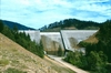
Upper Stillwater Dam – Utah
The design for Upper Stillwater Dam departed from all previous RCC dams in the US with respect to the RCC mixture proportions and design concept. Whereas the mixes for all seven previous RCC dams might be categorized as lean RCC mixes, Upper Stillwater used a high paste mix. Its predominate RCC mix contained 79kg/m3 of cement and 172kg of Class F fly ash, or a total of 251kg of cementitious materials. Upper Stillwater also had a wetter consistency as evidenced by a Vebe consistency (ASTM C1170) time in the 15-20 second range. The RCC mix with two-inch maximum size aggregate might be termed an ‘excess paste’ mix. This RCC mixture surpassed the minimum design direct tensile (180 psi) and direct shear (300 psi) properties at the life lines at one year.
A minimum compressive strength of 3000 psi was desired at one year. After ten years, cores indicated the main interior dam mix had exceeded 6700 psi due mainly to latter age effects of the 70% pozzolan (fly ash) content.
This design concept called for the RCC mass to act as the water barrier with the air-entrained slip-formed facing serving as a form, and also providing durability at this cold site in the Utah mountains where the mean average temperature is 1.7º C. Seepage performance through the high strength RCC mass has been excellent.
The problem has been leakage through cracks through the RCC section. Three cracks contributed to most of the leakage through the dam.
No transverse contraction joints were included in the design. Installation of initially proposed waterstopped joints at 15ft (4.6m) centers in the slip-formed concrete upstream face was expected to complicate the placing operation and thus increase cost. With slip-formed concrete facing elements, producing a weakened plane is no problem. It is the sealing of the joint that has proved to be expensive.
A finite element thermal analysis predicted cracking, but the analysis determined the cracks would not penetrate the RCC mass by more than 20ft (6m). Then, because the reservoir would be lowered annually, it was thought the cracks could be repaired from the upstream face, if needed. It has been theorized that the major cracks may have been initiated by a horizontal downstream movement in the foundation of 10mm after the reservoir load was applied to the entire structure.
Crack repairs have been accomplished on several occasions by the US Bureau of Reclamation with varying results.
In 2004, a major grouting and crack leakage repair program was initiated. Seven cracks in the dam were chemically grouted with drains installed. In this case, hydrophobic polyurethane grout proved to be more successful than the previously used hydrophillic polyurethane chemical grout. An additional seven cracks only had drains installed to relieve water pressures in the dam.
Three of the wider cracks in the dam received a more positive cutoff. Fourteen foot (4.3m) wide slots with a minimum width of 4? inches were drilled in the RCC across each major crack. Then a stainless steel ‘corrugated’ membrane was installed in 20ft (6m) sections from the dam crest that were welded together to provide a continuous water barrier. The area in the slot on either side of the steel membrane was the filled with an asphalt/cement mix. All indications are that this repair programme will provide the long term fix to the cracking problem at Upper Stillwater Dam.
Conclusion
The development of the RCC dam in the US in the early 1980s was met with a great deal of optimism and promise. Design engineers and owners became enthused with this new method of building a concrete dam more rapidly and at less cost by using construction techniques previously applied to building embankment dams. Still, the inherent safety of a concrete dam was maintained.
During the first five years of RCC dam development in the US, eight dams greater than 50ft (15m) in height were designed and built. Time and time again, more rapid construction and significantly less cost than a conventional concrete gravity dam were proven. Many features in the design of these dams were positive.
However, in all but one case (Winchester Dam), certain features of the design did not perform as anticipated. The perceived problems included excessive seepage through the RCC mass, leakage through transverse cracks, cracks due to differential settlement, deterioration at the downstream face due to freeze-thaw and wet-dry cycles, and the leaching of calcium hydroxide to form calcium carbonate deposits where it meets the air. In no case did the problem encountered jeopardize the safety of the dam.
Many of these problems required maintenance following completion of the dams. The performance of this first generation of RCC dams in the US was usually well publicized. The designers of future RCC dams owe a great deal of gratitude to the pioneering efforts of these early RCC dam designers. Lessons were learned that would be applied to more recent RCC dam designs.
Because of the noteworthy efforts of these pioneers, designers of RCC dams nowadays can develop a concrete dam that will perform well with little anticipated future maintenance. The cost has, however, risen somewhat for these improved designs.
Kenneth D. Hansen, P.E., Senior Consultant, Schnabel Engineering, 2280 South Xanadu Way, Suite 250, Aurora, CO 80014. Email khansen@schnabel-eng.com
This paper is based on a presentation given at Dam Safety 08, organised by the Association of State Dam?Safety Officials. For further information visit www.damsafety.org
| Lessons learned |
| The main lessons learned from the design and subsequent performances of these eight first generation RCC dams in the US are: |