Methods of construction
14 February 2006Timothy P Dolen and John Trojanowski review the methods and equipment used during the construction of five service and emergency spillway structures by the US Bureau of Reclamation
The US Bureau of Reclamation (USBR) has the responsibility for the safety of its dams in the western United States and others as requested, primarily by Department of the Interior agencies. Funding for safety modifications is administered as a part of its dam safety programme, including reconstruction of emergency and service spillways. USBR has used roller compacted concrete (RCC) for the design and reconstruction of five spillways. RCC has many benefits, including reduced cost, rapid construction, and the ability to fit a variety of configurations. Placement rates are both design and equipment sensitive, and proper planning and selection of construction methods are essential to a successful job. USBR spillway construction projects have used a variety of methods for batching and mixing, transporting, placing, and compacting RCC. During these construction projects, several ‘choke points’ have been identified that can impede construction performance.
RCC for spillways or mass construction
RCC spillway construction differs from mass RCC construction in a number of ways. RCC spillways are normally configured as a series of one-lane wide steps placed parallel to and up the slope of an embankment or as a trapezoidal channel with stepped side walls, or both. Except for the spillway basin floor or apron, the volume of RCC per lift is much less than for mass RCC dams. Thus, common traffic patterns for placing mass RCC dams may not apply to spillways. Often hauling, placing, and compacting equipment have only one entry point and travel is over a narrow, previously placed and compacted lane. There may not be a turn-around point and hauling traffic is restricted to moving both forward and backward for transporting to and returning from depositing each load. Access for locating batch plants and haul roads may be more restricted. Sloping faces present more problems for transporting RCC because each additional lift reaches up vertically and out horizontally from the invert due to the side-slope. In addition to construction costs, the economy of an RCC spillway alternative depends on the flow, design head, embankment height and crest length.
Performance objectives
USBR RCC spillways require many of the same performance objectives as conventional spillways. The design and selection of materials and mix designs are influenced by some of the following performance objectives:
• Hydraulic performance – to meet hydraulic performance requirements, flow surface tolerances and finishes must be considered. Bond is normally required between successive lifts and drains with sufficient redundancy are also provided to relieve uplift pressures. RCC spillways are primarily low head structures with relaxed surface tolerances as compared to those with high velocity flow surfaces.
• Long-term durability – USBR structures are subjected to a variety of severe durability environments in the western states. USBR considers long-term durability essential for continued operation and safety. RCC mixtures have used conventional concrete graded aggregates for improved workability, higher compressive strengths, erosion resistance, and freezing and thawing durability.
• Constructability – RCC structures should be designed with particular emphasis to accommodate construction equipment needs and safety requirements. The specifications and construction plan should match the placing rate to the design requirements for achieving bond between lifts.
• Economy – Economical designs should consider both initial construction costs and long-term performance. Reduced width of placing lanes to decrease materials volume may not materialise as a cost savings if it slows placing rates.
Design and layout
Design loads such as uplift and duration of operation may influence the overall RCC thickness and whether bond is required between lifts. The width of placing lanes has ranged from 8 to 10ft (2.4-3m) on side slopes, depending on bonding requirements, safety, economy, and constructability. Each lane should be sized with an anticipated loss of 1-2ft (0.3-0.6m) of surface area caused by subgrade contamination, insufficient exterior edge compaction, and equipment travel requirements. RCC spillways should be designed in multiples of ‘bull-dozer widths’. The obvious minimum compacted lane width is one truck or dozer width plus at least 1ft (0.3m) for safety. Lanes should be rounded where possible and widened slightly for safety at turns. Acute angles should be avoided so trucks, dozers, loaders, and rollers can turn without having to back up. Sudden sharp turns that prevent equipment from operating safely and efficiently should be avoided. If possible, 90° turns should be rounded or made by a series of chords.
Unformed RCC
The slope and maximum height of sides above the spillway invert may eventually dictate the transporting and placing methods. One side of the 50ft (15.2m) high spillway walls at Ochoco dam, near Prineville, Oregon was compacted on a 0.8:1 slope to minimise the cut into the abutment. This is considered about the steepest slope for unformed RCC. Good surveying and simple striping with spray paint is usually all that is necessary to guide equipment operators. Complex spillways with variable slopes require better survey control. The higher and steeper side slopes benefit from mechanical edge compaction due to safety considerations. A slope flatter than about 1.5 to 1 is more desirable from a safety standpoint, but quickly limits the reach for conveyors as an option for transporting RCC. Most RCC spillways do not form the side slopes. However, USBR has successfully formed a compacted, all-RCC, stepped spillway face on a 0.8 to 1 slope for Camp Dyer diversion dam, near Phoenix, Arizona (Hepler, 1992).
Control structures
Most spillways have upstream control structures such as a weir, ogee crest, or even some kind of regulating gates. In general, a low head weir may be constructed with RCC. Longer RCC control structures may experience cracking that can result in excessive seepage. If a watertight control structure is needed, a structural concrete cap or control structure should be considered. Structural concrete can be reinforced and can contain embedded waterstop to control cracking and seepage. The reservoir upstream from the control structure can also be a source of seepage. Cutoffs into the foundation and drainage downstream from the cutoff can be used to control and manage foundation-related seepage.
Drains and embedments
The location and placement of drains is an important design issue. Most large spillways will have foundation drains to relieve uplift pressures and to safely remove water that enters the foundation. Since it is usually not practical to install contraction joints with waterstops in RCC, open contraction joints or cracks in the RCC may allow seepage to enter the foundation during flow conditions. Voids may develop in erodible soil foundations if the seepage flow through the joints or cracks is not properly filtered and drained. Foundation ground water may also need to be filtered and drained. Stagnation pressures at open joints or cracks (Johnson, 1976) can also result in spillway failure due to foundation erosion or hydraulic jacking (Trojanowski, 2004). Drainage combined with thicker, larger RCC placements can counteract potential uplift pressures.
If the foundation drains are placed above the excavated foundation (and into the RCC) they can create a reduced cross section in the RCC. In some spillways this may be a desirable design detail because the reduced cross section can initiate a crack, and thus produce a contraction at a controlled location where a filtered drain has been placed. If this cracking is undesirable, the drains can be placed in a trench below the foundation surface, or low profile flat drains can be used. Twelve by one-inch (30 by 2.5cm) flat drains were placed on top of both the foundation rock and subgrade at Ochoco dam and at Many Farms dam, located on the Navajo Nation, in Arizona. At Cold Springs dam, near Umatilla, Oregon six inch (15.2cm) diameter drains installed in the first lift of RCC also acted as crack inducers. Care was taken to carefully place RCC around these round drains to prevent movement during the spreading of the RCC and crushing during the compaction. Drains should be carefully located so they will not be crushed by equipment. Crack inducers and instrumentation are usually installed after the RCC is compacted. For thick RCC placements (several lifts thick) it is not necessary to install crack inducers at every lift. Steel crack inducers and instrumentation were installed on alternating lifts at Pueblo dam, Colorado to avoid interference.
Other design considerations
RCC may be used in plunge pools and stilling basins such as the case at Pueblo dam. High impact pressures or high velocity flows over unprotected RCC surfaces can result in structural damage. RCC lifts that are weakly bonded can progressively fail as flowing or plunging water enters the lift lines through unprotected cracks or joints. The RCC plunge pool at Pueblo dam was capped with reinforced structural concrete that was anchored to the RCC mass below. The RCC and structural concrete had matching contraction joints and waterstop was placed across the formed contraction joints in the structural concrete. This detail was designed to prevent high pressures due to the plunging spillway flows from entering the RCC where it could cause damage. The hardened RCC section was allowed to shrink and the open contraction joints were then successfully grouted using conventional grouting methods and equipment (Aberle, 2000).
RCC mixture design
The choice of mix design is often categorised as either the concrete approach or the soils approach, as wet mixes versus dry mixes, or at optimum dry density versus optimum consistency (Hansen, 1991). The authors’ preference is to differentiate as more workable or less workable based on whether a mixture has a measurable Vebe consistency according to ASTM C 1170 versus a mixture compacted at optimum dry density according to ASTM D 1557(ASTM, 2001). Although any mix or gradation can be proportioned for optimum dry density or consistency, USBR has followed a path of proportioning mixtures for optimum Vebe consistency, ranging from 15 to 30 seconds and using concrete graded aggregates. Some of the benefits obtained and properties of these mixtures are as follows:
• The sand and coarse aggregate can also be used for conventional concrete, filter and drain material, and RCC aggregate; requiring only two or three common stockpiles for the job.
• Mixtures with clean aggregates usually have a lower moisture content at the same consistency than mixtures with 5-10% minus No. 200 fines. This reduces drying shrinkage, decreases the cementitious materials content for a given strength, or increases the strength for the same cementitious materials content.
• Mixtures proportioned with clean aggregates and a measurable Vebe consistency should have a paste volume (water, cement, pozzolan, and entrained air) in excess of the aggregate void volume to provide the necessary lubrication between aggregate particles and reduce segregation.
• Mixtures with excess paste compact more easily under vibration, improving bond potential between lifts.
• Compressive strength follows established trends for water to cement plus pozzolan ratios. The cement:pozzolan ratio influences lift joint maturity and rate of strength gain.
• For mixtures proportioned with a Vebe consistency of 15 to 30 sec, the mixture with clean sands has significantly higher strength than ‘all-in’ road base gradations at the same C+P content.
• Mixtures with clean aggregates can be proportioned with entrained air. Entrained air significantly increases mix workability, with less water required for the same consistency. Although the air void structure is not the same as conventional concrete, entrained air in RCC significantly improves freeze-thaw durability (Dolen, 1991).
Choke points
Choke points are interruptions in construction productivity caused by a variety of conditions, such as limited accessibility, design layout, RCC construction methods, equipment selection, or combinations of all of these. Some of the choke points encountered on our jobs are as follows:
• A sharp, acute turn on 1-1/2:1 side-slopes at Cold Springs dam spillway caused equipment to stop and turn around during placement. This could have been avoided if the turn had been rounded.
• RCC ‘baffles’ across the spillway plunge pool at Ochoco dam – designed to maintain sufficient tailwater depth – were difficult to construct, and had to be reconstructed. Insufficient surveying led to difficulties placing RCC on changing side slopes.
• Difficulties batching for small batches of RCC at Pueblo dam spillway modification drastically reduced batch plant capacity. The low placing rate required significant additional lift surface preparations that were complicated by freezing overnight weather.
• A sloping transfer conveyor at Many Farms dam spillway was unable to match the capacity of the batching/mixing plant and the telescoping conveyor used to transport the RCC. Again, this led to more frequent cold joints and the associated additional lift surface cleanup.
Some choke points are obvious, while others take a particular set of circumstances to show. The task for both designers and contractors is to design the spillway and select equipment and methods that will allow placing ‘in harmony’, avoiding these costly choke points.
Equipment and construction methods
RCC placing rate
Lift joint bond is enhanced by placing multiple lifts per shift and by two-shift construction. The batch plant capacity and equipment placing methods should be sufficient to place multiple layers each shift without stopping for costly lift surface preparation. Normal lift surface preparation involves air or water jetting or vacuuming. If the schedule requires a delay in placing and the resulting cold joint, the lift surface cleanup crew should be scheduled one to two hours before RCC placing resumes. High-pressure water jetting is often specified to clean hardened, cold joints followed by vacuuming and a bonding mortar placed no more than 50ft (15.2m) in front of the fresh RCC. The time limit for cold joint cleanup required by specifications can change, depending on the design requirements for lift-line bond, RCC mix design, the cement to pozzolan ratio, and ambient exposure temperatures. The delivery, placing, and spreading of bonding mortar often causes delays in RCC placement and decreases the lift placing rate as much as 50%. As an alternative, the bonding mortar may be replaced by an RCC ‘Monday mix’ of workable consistency with about 20% higher cementitious materials content. Documentation of lift surface bonding at Upper Stillwater (gravity) dam verified that a clean, vacuumed lift surface could meet high bond strength requirements without the need for a bonding mortar even when exposed for more than 24 hours (Dolen, 2003).
Batching and mixing RCC
There are three primary types of RCC batching systems: (1) conventional weigh batchers, (2) continuous volumetric batchers, and (3) continuous weigh batchers. Mixers include conventional drum, batch paddle (or ‘compulsory’) mixers, and pugmills. Either batching system can feed to either mixer type. Typically, weigh batchers feed either drum or compulsory mixers and continuous batchers feed compulsory mixers or pugmills. Based on our experiences, weigh-batch plants take considerably longer to set up than the self contained, continuous plants. If time is short, the self-contained, continuous plant is the way to go for RCC. We have tried to use a continuous weigh plant for conventional concrete with poor results.
USBR has had good experiences with all three batching systems for RCC. The coefficient of variation of RCC compressive strength cylinders is summarised in Table 1 for the three batching systems. The weigh-batch system has the lowest coefficient of variation even though the RCC contained entrained air. Weigh-batch systems are best when using admixtures and for combining conventional concrete and RCC batching. One recent problem was encountered at Pueblo dam spillway modification with a weigh-batch system when the batch size (4yd3[3m3]) was only 40% of the batcher size (12yd3[9.2m3]). The inability to consistently batch cement for the reduced batch size decreased the mixing plant rate to about one third of the rated plant capacity. It should be noted that RCC mixtures have about one half the cementitious materials content of conventional concrete. A conventional, weigh-batching system may not be able to meet the same weigh scale tolerances for a small batch of RCC with a low cementitious materials content. USBR practice is to test the RCC fresh properties throughout the placement and adjust the moisture content to maintain an optimum Vebe consistency of about 15 to 30 seconds. The density of fresh concrete is used to compute the yield of RCC ingredients for each shift from the recorded batch plant quantities. Compressive strength test cylinders are normally cast once during each shift of concrete placement.
USBR has used both continuous volumetric and continuous weigh-batching systems. The continuous weigh-batching plants often combine a volumetric proportioning system with a belt scale ‘weighbridge’ added just before feeding the combined materials into the mixer. For both systems, it is essential to make sure the moisture content of the aggregate feed does not vary. If the aggregate feed and moisture content are consistent, both plants perform well. Specifications normally require 50 to 100% of aggregates for the job to be furnished before beginning RCC construction to allow the moisture content of aggregates to stabilise. Continuous plants should not be run intermittingly. Surprisingly, this often happens because other placing activities become choke points. A continuous, weigh-batch plant used at Cold Springs dam had belt scales for aggregates and a cement weigh–sensing element. The cement hopper also rested on load cells, providing a check for the weight-recording system. The aggregate bins had essentially volumetric adjustable gates that fed onto the main aggregate feed conveyor with belt scales. It is helpful to run the combined aggregate flow over a small feed screen to blend the sand and gravel on the main conveyor prior to weighing. This was not done at Santa Cruz dam, near Espanola, New Mexico, and the belt scale weight surged with ‘lumps’ of aggregates piled on the feed belts.
The authors’ primary concern with continuous volumetric plants is the lack of control of input feed due to changes in materials properties. Continuous volumetric feed is normally monitored in revolutions of vanes or belts. If something affects the volume being fed onto the belt feeding the mixer, there is no real-time monitoring sensor on the input end of the plant. There may be an exit belt scale for checking the output quantities. It’s unfortunate that the typical moisture content of aggregate stockpiles is near the most sensitive part of aggregate ‘bulking’ curve (Neville, 1997). The variability caused by sand bulking was one of the reasons why USBR changed from volumetric to weigh batching in the 1920’s. The results from Ochoco dam show some of the problems with variability of continuous volumetric plants. The overall variability was high. However, much of the early variability occurred due to changes in aggregate moisture and gradation. After a new source of sand was delivered to the site at a consistent moisture content, the aggregate feed to the plant was more consistent and it operated well with frequent checks for fresh properties and mix yield. Recently, more sophisticated input monitoring systems have been installed on continuous volumetric plants and are now capable of making on-the-fly moisture corrections.
Drum mixers clearly have longer mixing times than paddle type mixers, and for the same batch size have a lower placing rate. However, many drum mixers have larger sizes that make up for the longer mixing times. If the plant is set up correctly, a drum batching-mixing system can be used for both conventional concrete and RCC. This can be advantageous over setting up two plants or if there are substantial quantities of conventional concrete or if the local ready mix plant is too far away. Sticky RCC mixtures, those with appreciable aggregate fines, build up inside drum mixers. RCC mixtures with clean aggregates work well in both drum and paddle type mixers. The paddle-type mixers, compulsory and pugmills are ideal for mixing RCC. The compulsory mixers usually have bottom dump doors and fixed mixing times and the pugmills are tilted to adjust the mixing time. A gob hopper can effectively supply intermittent hauling units without stopping continuous plants. The gob hopper should be at least as large as the hauling unit capacity. Surge piles not contained within a hopper are undesirable due to segregation of coarse aggregate and the loss of workability in the RCC mixture.
Transporting RCC
Three common methods of transporting RCC include hauling trucks, front-end loaders, and conveyors. Hauling trucks have succeeded where there is sufficient operating room for backing up and dumping RCC. In some instances, trucks and front-end loaders provide the needed flexibility for transporting and placing; trucks for placing in the wider invert sections and front-end loaders on narrow placing lanes parallel to, and up the sloping faces. End-dump trucks have larger hauling capacity, resulting in less travel over lift surfaces.
Front-end loaders have tighter turning radii and can operate effectively both forward and backward along the narrow lanes. The smaller capacity of loader buckets requires more trips over the compacted RCC surfaces. The farther the batch plant is away from the placing site, the less efficient front-end loaders become as hauling vehicles. Tight turning and heavy wheel loading of loaders can damage compacted RCC surfaces, requiring additional lift surface preparation before continuing placing. This is particularly true if the loaders are equipped with 'lugged' tires. It is suspected that intense traffic patterns over the compacted surface of hardened RCC decreased the bond strength just below the top of the lift surface at Pueblo dam spillway modification. Front-end loaders do have a place in RCC spillway construction. Higher and steeper side slopes usually dictate hauling with loaders over trucks and conveyors. This is even more necessary if there are turns in the spillway where trucks cannot safely back up.
If the spreading equipment is not equipped with sidewalls, the dumped RCC will spill out over the previously placed and compacted RCC in an hourglass pattern. This was the case at Vesuvius dam, near Ironton, Ohio for an RCC overtopping project. It takes considerable manual labour to shovel the spillage back onto the placing surface and there is inevitably wasted concrete. Ideally, trucks should have some end-gate control to prevent piles of dumped RCC exceeding 3ft (0.9m) high. A simple system of side ‘wings’ and controlled gate was used for RCC at Upper Stillwater dam, near Duchesne, Utah. The even edges and level dumped surface needed minimal finish spreading with one D-4 dozer to achieve a 12 inch (30.48cm)] [compacted] lift thickness for 1.5Myd3 (1.1Mm3) of RCC.
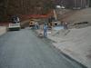
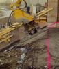
Two unique methods of transporting RCC were used at Cold Springs dam and Many Farms dam spillways and are shown in Figures 1 through 3. At Cold Springs dam spillway, a continuous batching/mixing plant fed a gob hopper and then hauling trucks transported the RCC about 1/4 mile (0.4km) to the 900ft (274m) long spillway. The trucks dumped into a second hopper constructed from the back half of a scraper as shown in Figure 1. The RCC was picked up by track-hoe bucket, placed directly in front of the dozer as shown in Figure 2, and spread to 1ft (0.3m) thick [compacted] lifts. The track-hoe was able to reach up 30ft (9m), and about 50ft (15m) horizontally on 1-1/2:1 side slopes. When the dozer travelled away from the reach of the track-hoe, it just pulled the scraper along with it. This was a very successful match of mixing, hauling, and placing equipment. Track-hoes provide similar benefits plus the ability to move beyond the reach of fixed or telescoping conveyors and are well suited for spillways with limited access. Conveyor transporting can be used in combination with other hauling equipment or stand-alone, placing directly in front of spreading equipment. At Many Farms dam, a Telebelt conveyor received RCC from a hopper fed by a front-end loader and transported the RCC directly in front of a dozer as shown in Figure 3 (US Bureau of Reclamation, 2001). The conveyor was able to reach the entire placement, more than 100ft horizontally and 15ft (46m) vertically. The capacity of conveyors is affected by belt width, belt speed, and by the conveyor slope. The dry nature of RCC can significantly decrease the capacity of sloping conveyors, as the aggregates tend to tumble downward due to gravity. A short, sloping, transfer belt from the feed hopper was unable to match the capacity of the horizontal belt, decreasing the placing rate.
Spreading RCC
Bulldozers are by far the equipment of choice for spreading RCC. Most dozers have extended, side ‘wings’ to form a spreader-box to prevent spillage from the hauling vehicles. At Cold Springs dam, a vibrating-plate compactor was added to the outside of the spreader box as shown in Figure 4. The fresh RCC was compacted in place at the outside edge, eliminating the need for additional edge compaction. This design has great promise with some modifications such as better capability to adjust for variable lift height and changes in alignment. This system required a workable mix with a measurable Vebe consistency of 30 seconds or less. None of the spillways constructed by USBR have utilised soil cement spreader boxes. However, asphalt spreaders have been used for some RCC/soil cement facings. This equipment appears best suited for long, straight applications.
Lift surface cleanup and cold joint preparation
USBR specifies three types of RCC lift surface conditions depending on the time interval between placements. Type 1 or standard lift surface treatment is for multiple lifts per shift with 4-8 hours between lifts. This lift surface requires low-pressure, air or air/water jetting and/or vacuuming prior to placing the next lift. Type 2 or cold joint treatment requires the same type 1 preparation, plus vacuuming and applying a bonding mortar. This is for lift surfaces exposed from the end of type 1 limits to 24 to 48 hours after placing. Type 3 joint treatment follows the type 2 limit, and requires high-pressure, water blasting followed by vacuuming and applying bonding mortar. The time limits apply to mixes with 25 to 50% pozzolan, and may change due to the mix design and ambient exposure conditions. Mixes with high pozzolan contents or those placed in fall or winter will usually have longer time limits. Mixes with 100% cement or those placed in warm weather usually have shorter time limits. Bonding mortar can be supplied by transit mix truck, loaders, tractor loaders, pump, or crane and bucket and spread with rakes or squeegees. Skid-steer loaders are not recommended because they tear up the compacted lift surface.
Compacting RCC
Most of the RCC spillways have been compacted with single-drum, vibrating rollers. These rollers have greater maneuverability than double-drum rollers, particularly if there are steep access grades. The single-drum rollers require more passes than double-drum rollers for equal compaction. The number of roller passes is usually dictated by the consistency of the RCC as measured using the Vebe apparatus (ASTM C 1170). Mixtures with a measurable Vebe consistency of 30 seconds or less usually compact to within 99% of their design density in four to six roller passes. Less workable mixtures require more roller passes. There is a tendency to try to dry up the mixture so the freshly spread RCC is more stable for equipment travel. A less workable mixture with too low a paste volume may require more roller passes and can segregate, forming rock pockets, and not bond to the preceding lift.
Unformed edge compaction
A number of methods have been used for compacting the outside edge of RCC spillways. This usually involves hand-operated compactors or vibrating plates attached to hydraulic equipment. As stated above, the vibrating plate compactor attached to a dozer spreader box was all that was necessary to compact the outside edge of Cold Springs dam spillway to about 95% of the maximum density. The vibrated edge also makes the outside more stable for rollers compacting the top surface. This provided more safety and eliminated the need for one or two labourers. USBR has specified vibrated, compacted faces on all of its spillways. If not compacted, about 1ft3 (0.03m3) of RCC is wasted per linear foot of travel. The un-compacted face costs about US$3 to $4 per square foot of facing. The cost of compacting the face is thereby offset by the material volume savings. Loose aggregates could also cause an abrasion-erosion problem depending on hydraulic conditions.
Three types of vibrating plate compactors were attached to track-hoes to compact the edge of Ochoco, Pueblo, and Many Farms spillways. The different plate compactors provide a good comparison of equipment and methods. At Ochoco dam, a standard ‘hoe-pack’ compactor about 18 by 24in (45.7cm-61cm) was attached to a track-hoe. Initially, the track-hoe reached up from the invert to push against the unformed, sloped face. This had a tendency to push up the fresh RCC and left many impressions on the face. At Pueblo dam, a larger 2 by 3ft (0.6m-0.9m) plate was used for compacting the 2:1 sloping face and the track-hoe operated from the top of the freshly placed lift, as shown in Figure 5.
Compacting from above provides the operator with much greater visibility and the resulting face has a much more pleasing appearance. The large plate could overlap the preceding compacted face, which was particularly effective for placing multiple layers of fresh concrete. A small Cat excavator with a custom-fabricated vibrating plate was very effective at Many Farms dam spillway. This 2ft (0.6m) long by 1ft (0.3m) high plate, shown in Figure 5, provided downward pressure on the top 6 inches (15.2cm) of the lift as well as side pressure leaving a pleasing appearance with very close tolerances. It is the author’s opinion that small track-hoes equipped with a vibrating plate compactor provide the most desirable and economical compacted edge surface for RCC spillways.
Hand operated plate compactors are often used on small jobs. This includes both ‘jumping-jack’ tampers and vibrating plate compactors at Vesuvius dam, Ohio. This is time consuming, backbreaking work, and not very effective for compacting deeper than six inches (15.2cm) from the outside edge. Labourers have great difficulty maintaining the proper angle normal to the surface due in part to the variable width and density from end-dumped RCC. This surface often erodes away leaving an exposed aggregate surface.
Recommendations
USBR’s experiences have demonstrated a variety of successful construction methods for RCC spillways. Based on these experiences the authors recommend the following equipment and methods for RCC spillway construction.
• Batching and mixing: A continuous, weighing plant for speed and the ability to record input mix parameters. The plant should feed to a gob hopper if necessary, for intermittent loads feeding hauling vehicles.
• Transporting: End dump trucks that can dump into an intermediate hopper or directly in front of the dozer. Front-end loaders only for operating along sloped sidewalls. Conveyors if the entire placement can be reached with few set-ups.
• Spreading: A dozer equipped with a spreader box and a side edge compactor for unformed, sloping faces.
• Compaction: A double-drum roller for wide, open areas; otherwise a single-drum roller.
• Edge Compaction: A small track-hoe equipped with a vibrating plate compactor. The plate should be about 3ft (0.9m) long, 1ft [0.3m] (one lift) high, and have about 6 inches (15cm) of top down-pressure.
Author Info:
Timothy P. Dolen, PE and John Trojanowski, PE are both civil engineers from the US Department of the Interior, Bureau of Reclamation at the Technical Service Center in Denver, Colorado, USA. For more information, please visit USBR's website at www.usbr.gov, or email: tdolen@do.usbr.gov or jtrojanowski@do.usbr.gov.
This paper is printed with kind permission of the Association of State Dam Safety Officials. For further information, please visit www.damsafety.org.
TablesTable 1