Power electronics for hydro plants
19 September 2006Hans-Joerg Herzog reports on the major applications of power electronics in hydro power plants
In hydro power plants, the most frequently used applications of power electronics are Static Frequency Converters (SFC) and Static Excitation Systems (SES). SFC’s are commonly used for soft-starting of pump/turbine sets in pumped storage plants, where the SFC provides a source of adjustable frequency/voltage for starting the pumps and in adjustable speed applications, in which the pump/turbine set can operate at adjustable speed and the SFC converts the output of the generator to match the frequency/voltage of the local power system.
Why adjustable speed applications?
The following operation conditions might trigger the idea to consider an adjustable speed instead of fixed speed pump/turbine operation:
•Increased total plant operation time by allowing turbine operation when head levels are low without the risk of high maintenance cost due to cavitation.
•Optimisation of turbine efficiencies over varying head levels and water flow conditions.
•Pumping applications where power taken from the local grid must be limited.
•Stream-bed stability below dams in order to avoid river bed damage.
•Increased environmental concerns about damage as a result of turbulence near the turbine blades when operating at certain head levels.
Selection of an SFC for an adjustable speed application
LCI-type SFC
The SFC is electrically connected to the output of the generator. The electrical losses, which are about 1% of the SFC’s nominal rating (excluding eventual transformer losses), are usually minor compared to the increased plant efficiency which results from the ability to operate at different speeds. When not needed, i.e. when the unit can be operated at rated speed, the SFC is normally bypassed - using the appropriate electrical switchgear.
Sub/super synchronous converter cascade
If changing the pump/turbine speed within smaller ranges is acceptable, this SFC application might be more desirable because of the lower costs and higher efficiencies. Another advantage of this system is the possibility to control the reactive power by over or under-excitation of the rotor winding. The SFC has to remain connected to the rotor field as long it is used for speed control or reactive power control.
So, when does an adjustable speed application become beneficial? To improve the overall performance of an existing plant, the addition of an SFC can result in more efficient operation at a wider range of head and water conditions. Also, for increased plant efficiency and additional revenues in new installations – an SFC allows higher design head for the pump/turbine than for a fixed speed application. Since the SFC permits operation of the pump/turbine set below its design speed, the unit can be operated at its optimum efficiency as the head level and water conditions fluctuate.
How to start pump/turbine sets in pumped storage plants
In this type of application, an LCI-type SFC utilises power from the local power system. The output of the SFC is connected to the synchronous machine and the frequency is raised together with voltage from near zero values. The synchronous machine follows this increase of frequency/voltage up to full speed at which time the unit is synchronized to the local power system. Then, the SFC is disconnected and the machine begins to operate in the normal pumping mode. During all SFC operations, the pump/turbine is dewatered, which allows the SFC to be designed with about 5% of the nominal generator rating.
In multi-unit plants, one SFC is switched from unit to unit to control the start-up process of the entire plant, including automatic acceleration and synchronization.
An SFC provides several advantages over the use of ‘pony motor’ starting systems:
•Only one starting device is required for several pump/turbine units versus one per unit.
•Maintenance work can be accomplished while the pump/turbine unit is running, avoiding loss of revenues during maintenance shutdown.
•Less maintenance is required.
Another method of starting pump/turbine units is ‘back-to-back’ starting, in which case one unit is operating as a generator and provides power to accelerate a second unit operating as a motor. However, the last unit in the plant cannot be started as a motor with this method. Further, special attention must be given to the acceleration process to avoid high oscillation forces or loss of synchronism (‘out of step’ condition).
Alternatively, motor/generator units can be started ‘across the line’, i.e. the unit is connected to the power system, either directly or with an additional impedance to reduce electrical stresses on network, the machine and mechanical stress on the shaft string.
Benefits of SFC starters
One of the major benefits of an SFC is that it can accelerate a pump/turbine unit from zero to full speed without subjecting the unit to detrimental high inrush currents or excessive damper winding heating. Instead, the SFC provides a ‘softstart’ by ‘ramping up’ the frequency together with the voltage as the units accelerates. In comparison with the cost of early generator rehabilitation as a result of ‘across the line’ starting, an SFC can be very economical.
Beside this, there are other advantages of an SFC starter to be taken into consideration:
•Wear-free electrical breaking of a running unit from synchronous to zero speed while feeding the mechanically stored energy of the generator back into the local power system, thus enabling a fast change from pumping into generating mode or vice versa.
•Operation of the pump/turbine set at any speed required for convenient pump/turbine diagnostics.
•Synchronizing of generators to a power system with unstable system characteristics where use of the governor for speed control during synchronizing is ineffective because of a low flywheel effect ratio.
•Prevention of reverse power flow during a transition from synchronous condenser operation to generator operation in small power systems.
•Capability to feed additional instantaneous power into the network in case of an emergency by using the SFC and the pump/turbine set for ‘spinning reserve’ capability. The enormous rotating energy of the pump/turbine set can be transferred to the local power system via the asynchronous link provided by the SFC, during transition from synchronous condenser to turbine operation.
The principle of SFC
MEGADRIVE-LCI-type SFC
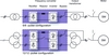
The SFC consists of two three-phase thyristor converters and a DC reactor in between. One converter is connected to the local power system with fixed voltage and frequency, the other to the stator winding of the synchronous machine with variable voltage and frequency. Each converter is capable of converting AC power into DC power, and vice-versa.
By connecting both three-phase bridges in series and decoupling them by means of the DC reactor, the SFC becomes an electrical asynchronous link between the synchronous machine and the local power system. For adjustable speed applications, one converter of the SFC converts the variable frequency/voltage power output of a generator operating DC power. The second converter converts the DC power into the synchronous frequency and voltage which matches the local power system. This SFC configuration is described as an LCI-type SFC (Load Commutated Inverter).
The same SFC can be used in reverse, taking the constant frequency/voltage of the local power system, converting it first to DC power, and then to AC power of variable frequency/voltage. This AC power can be used for starting a pump/turbine set or for adjustable speed applications when operating the units as pumps.
Whether used to convert power going into or taken from the local power system, the MEGADRIVE-LCI control is continuous from zero up to the maximum design frequency/voltage. Depending on the requirements, the SFC may be designed either to control speed or power output of the generator. When needed for the application, current and torque can be changed from zero to maximum values within a few milliseconds. Since there are theoretically no technical limitations for the size of an SFC, they can be designed for applications up to 100MW and above.
If the harmonic influence on the supply system and/or the electrical machine is a concern, a 12 or 24 instead of a 6-pulse converter design might be the appropriate solution.
Sub/super synchronous converter cascade
In the applications, also called ‘double fed’ design, the stator winding of a wound-rotor induction machine is connected to the local power system, and the rotor winding is connected to the output of a three-phase SFC. The amplitude, frequency and phase angle of the rotor current are controlled by the SFC, permitting independent control of the generator’s active and reactive power. Two quadrant (motor and generator) operation is possible at speeds above and below synchronous speed.
In this system, the SFC is used to control the rotor field winding instead of the stator winding. Therefore, the SFC can be smaller and less expensive and will have lower losses. However, the speed control range of a sub/super-synchronous converter cascade is limited to about 90% to 110% of the nominal synchronous speed during normal operation. For starting the unit as motor in pump operation, the generator stator will be short-circuited and the converter cascade will be operated as a normal SFC Starter.
Unitrol static excitation system
The excitation system has a major impact on the performance and availability of a generator or a synchronous machine in general. This statement applies to both Static Excitation Systems (SES), usually supplied from the machine terminals, or exciter machines, today preferably equipped with rotating diodes and controlled by an Automatic Voltage Regulator (AVR). As the size of an exciter machine grows inversely proportional with the machine speed, SES is the preferred method in larger hydro power plants.
The primary function of an excitation system is the supply of DC current with adequate safety margins to the field winding and the accurate and stable control of the stator voltage of a synchronous machine. However, for modern state of the art SES with a microprocessor-based controller this is just one of many control functions. Closed loop limiter circuits for field current, stator current, load angle etc. prevent the machine from being operated outside the permissible area. It is important to coordinate the settings of these limiters with the set values of the generator protection to make sure that the limiters intervene whenever possible before the protection circuits might shut down the machine.
As soon as the machine is connected to the network, controlling the terminal voltage is often no more the prime concern of the plant operator. Controlling the power factor or the reactive load on a pre-set value might be more important. Such controllers are of course also part of SES’s and can easily be activated if needed.
Power System Stabilizer – a key functionality
Another function that has become more and more important over the past few years is the Power System Stabilizer (PSS). Analyses of network blackouts have proven that properly adjusted voltage regulators together with PSS circuits might have prevented networks falling apart. Therefore, in many countries it is nowadays compulsory to equip excitation systems for larger generators with PSS. New systems have this function included in the software package, older systems must be updated with stand-alone microprocessor-based PSS.
In the past, all major suppliers of AVR and SES followed their own philosophy with respect to the transfer function and the included features of the PSS. Meanwhile, the PSS type 2A or the improved version 2B according to IEEE Standard 421.5 (2005) has become wide spread. The multi-band PSS (named PSS4B in said IEEE standard) developed by Hydro-Québec might become a new future standard for power stations operated under critical network conditions.
It is important that PSS suppliers have solid theoretical and practical background to provide analytical studies for the optimised PSS settings and to prove these settings in a closed loop with a model of a synchronous machine during factory acceptance tests.
Increased dynamic performance and availability
The dynamic behaviour of excitation systems not only depends on the control circuits but on other design factors as well. Important is the proper selection of the so-called ceiling factor (max DC output voltage divided by the adopted base field voltage). The ceiling factor of a SES can be increased to any still safe level for the generator field winding in order to meet tough dynamic requirements.
Another important aspect to take into consideration when selecting an excitation system is its availability. Any shutdown of a generator results in operation and production losses. Therefore, higher initial costs for an excitation system with redundant circuits often turn out to be a wise investment. However, redundancy should not only be limited to the power electronics (e.g. thyristor converter) but should be extended to the control circuits as they often prove to be less reliable than the power circuits.
Taking all this into consideration, a careful selection of the excitation system is important, not only for new installations but also to replace old exciter machines in existing plants.
New technologies support the service work
More powerful microprocessors set trends towards shorter commissioning time and easier maintenance. Real-time models that simulate the generator precisely can be integrated, enabling most of the settings off-line without the generator running. The connectivity of field equipment to the Internet will carry on in the future. This feature is interesting for remote diagnostics and system data collection. This enables the equipment supplier to assist the maintenance engineer in trouble shooting which can shorten the outage time of the machine considerably. There are other features supporting operation and maintenance in the future. Sophisticated local screens with their own intelligence will guide the maintenance engineer. Integrated event and disturbance recorders will provide important information for analysing faults and diagnosing components to be replaced.
Common power electronics control platform
ABB has developed a powerful controller, the AC800PEC, dedicated for all kind of power electronic equipment including SFC (LCI-type as well as cascades) and SES. It is fully compatible with ABB’s 800xA control platform. The application SW programming is done with ABB Control Builder based on IEC61161. UART, CAN and Ethernet supporting the fieldbus protocols CANOpen, Modbus-RTU and Profibus are the main options for communication with the plant control system. An additional possibility is Ethernet, using OPC protocol.
Author Info:
ABB Switzerland Ltd, Power Electronics & Medium Voltage Drives, CH-5300 Turgi, Switzerland. Email: hans-joerg.herzog@ch.abb.com.
For further information, visit www.abb.com/unitrol or www.abb.com/motors&drives