RCC
MIEL I
RCC record breaker
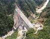
26 January 2004Humberto Santana and Eduardo Castell take a look at the story behind Colombia’s record breaking Miel I dam. Put into operation in 2002, the 188m high structure is currently the tallest RCC dam in the world.
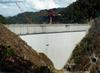
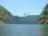
STANDING at 188m, Colombia’s Miel I is to date the highest RCC dam in the world. It was put into operation in April 2002 and broke the previous world height record of 136m. The dam is part of the civil works for the Miel I hydroelectric project.
The initial designs for the bid were made between 1992 and 1993. In December 1993, the bidding process for the project’s integral construction, including electromechanical equipment procurement and erection, was opened. The negotiations to define the financial conditions and requirements for the project were carried out from 1994 until 1997. Construction work began at the end of December 1997, and commercial operation of the plant followed in December 2002.
The detailed design of the project was carried out in parallel with the construction works between 1997 and 2001. The original schedule for project completion was 66 months, but it was actually completed in just 59 months.
All the RCC required for the dam’s construction, with a total volume of 1.75Mm3 was produced and placed in 25 months.
Initial alternatives considered
Initially a rock fill dam with concrete upstream face was considered, but this would have required the construction of a spillway with two big lateral tunnels and a considerable increase in the project’s cost.
Two other dams options were then considered; an arch concrete dam and an RCC gravity dam with the spillway incorporated in the structure.
Analysis of these alternatives led to significant construction cost savings of about US$60M (17% of the total project cost).
Although the arch concrete and RCC gravity options had similar direct construction costs, RCC was selected because it allowed the use of a shallower foundation, significantly reducing foundation work and diminishing the risks associated with the construction.
The first design considered was based on a stepped spillway in the downstream dam face, trying to use the steps produced by the placing of the RCC layers. This type of structure has the potential advantage of damping the flow energy reducing the additional works required for the dissipation structures located at the end of the channel. The hydraulic model results (scale 1:50 and 1:25) indicated flow energy dissipation of about 70% when the water fell down 2.1m stairs.
However, the solution adopted was a conventional spillway with a sloping chute channel and ski jump discharge, located on the downstream dam slope, mainly due to the lack of historical information about the behaviour of stepped spillways with a unitary volume of flow greater than 60m3/s/m and a hydraulic drop of 175m, which were the parameters required by the Miel I project.
Adopted solution
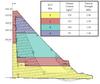
The final solution was an RCC Gravity Dam, with a maximum height of 188m in the axis, (200m from the lower foundation point). The dam had a triangular section with a vertical upstream face and a stepping slope downstream face with a grade changing from 1:1 at the bottom, to 0.4H:1V in the upper portion (average grade 0.86H:1V). The dam was divided into zones with different classes of RCC mixes, with low to medium cement contents ranging from 85–150kg/m3, according to the design stress levels.
In order to avoid an undesirable cracking level by thermal stresses, transverse contraction joints separated at 18.5m were used along the longitudinal axis, and also a longitudinal joint was built in the lower central part of the structure. The transversal joints were made by the joint inserter system, cutting the freshly placed RCC layers (0.3m thick) at an initial stage of compaction with a metal cutter fitted with a steel joint spacer that was left on the layer. The spacer was 0.25m and had a curved end for fixing it into the RCC layer.
The spillway was incorporated into the downstream face of the structure. It is conformed by a top bucket with a length of 65m, followed by a 176m length slope chute channel, with an average grade of 116%, and bordered by lateral convergent walls with a height between 4–5m. The channel ends with a ski jump with a radius of 15m and 33.4m wide. The discharge edge of the ski jump is 45m above the riverbed. To avoid cavitation damage, the channel was equipped with an aerator in the central part.
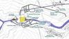
The dam is downstream of the confluence of the Miel and Moro rivers, in a narrow throat with favourable geological conditions.
To start with the civil works for the dam’s construction, the river was diverted through a tunnel located in the right buttress. The tunnel has a length of 543m and a cross section of 11 x 11 without any lining.
Together with the cofferdam, with a height of 50m and built with RCC of a low cement content (70kg/m3), this tunnel with a capacity of 1300m3/sec was designed to convey transients with a maximum return period of 10 years. The total direct cost of the dam and its annexed works was US$106.2M; equivalent to 62.8% of the civil works costs and to 38.2% of the project’s total cost.
Geotechnical design
The rocks found at the dam and complementary works (the intake, the conduction and the underground power house) are mainly hard and sound micaceous gneisses, covered by residual silty soils and colluvial deposits. They present a high foliation and dip angles, diaclases in defined patterns, andesitic, and pegmatitic dikes, and relatively thin sheared zones combined with superficial zones of intermediate thickness with stress relaxation and weathering.
The rock structure is favourable for the dam foundation, with the exception of a small amount of open diaclases produced by stress relaxation. Weak subhorizontal planes of importance were not found. The foundation treatment included the remotion of small unstable blocks in order to get a uniform foundation surface and to avoid stress concentrations. In addition to this, a deep grouting curtain down to 60m was made together with consolidation grouting to a depth of 20m.
The foundation rock geotechnical conditions were adequate for the RCC gravity dam. The hardness was medium to high, with moderate fractures, elasticity module in the range 15-25GPa, RQD greater than 80% with weathering traces, some discontinuity planes and moderate infiltration.
According to the seismic hazard study, the project is located in a medium zone, with earthquakes associated mainly with the Palestina fault. This is 16km from the dam at the closest point and could generate earthquakes measuring up to 6.0 on the Richter scale. The estimated focal depth associated with this fault is 45km. The horizontal acceleration for the Design Basic Earthquake was 0.22g and for the Maximum Credible Earthquake was 0.30g.
Consolidation and curtain grouting
Consolidation grouting with a depth of 20m was designed in order to improve the superficial foundation ground conditions, sealing the cracks produced by stress relaxation, and waterproofing the possible water infiltration sources.
A 40–60 m deep grouting curtain was made to close the cracks and discontinuities that are present deeper in the rock mass, to form a barrier for the water flow from the reservoir in the direction of the downstream face of the dam or toward the tunnels.
The contact grouting under the plinth, which is an apron like base slab in the upstream along the RCC dam face anchored to the ground, has great relevance, so a special device was designed to perform these works after the slab had been built and anchored to the terrain. The consolidation grouting also sealed the area between the plinth where the PVC membrane is anchored, and the deep grouting curtain.
The grouting drilling was made from the galleries located on the dam buttresses after the placing of the RCC.
This allowed the use of higher pressure because of the weight of the RCC mass above the buttress. With this procedure, the schedule of RCC placing could be made independent from the grouting.
The grouting intensity number (GIN) method was used for all the required grouting works, and was selected mainly for its efficiency considering the reduction in grout use and waste. After the primary grouting, second and third stages were injected according to the particular site conditions, the water infiltration test results, and the behaviour of the previous contact grouting phases.
Drainage
The drainage system for the buttresses and the dam body was based on a system of drilled drains that collects the infiltration and carries it into the galleries.
The drain holes are 7.6cm in diameter and are separated by 8m in the dam body and 6m in the buttress zones.
The PVC membrane installed on the dam upstream face has a special drainage system conformed by metallic channels fixed to the RCC with their corresponding discharge pipes to the galleries.
In the galleries, the infiltration water is transported through gutters located on the floor. Several measuring weirs were installed to measure the water infiltration flow.
Waterproofing
Due to doubts about the RCC watertightness, and to the possible uplift forces inside the dam body generated by the water infiltration between the RCC layers, an independent medium covering the upstream dam face was used to improve the impermeability.
For this purpose a PVC membrane from carpi was selected. In addition to this, the waterproof system was complemented by shallow and deep grouting curtains.
The union between the PVC membrane and the curtain grouting system was made through the plinth, where the PVC membrane is fixed. Like an additional measure to reduce infiltration, an enriched 40cm layer of RCC was placed on the upstream face. This layer made it possible to embed the metallic channels that support the membrane and the PVC seals between the dam contraction joints, without the use of conventional concrete.
The membrane design was based on the parameters obtained from the manufacturer certified tests. The coupling and fastening systems were used as given by Carpi, who developed and patented them. A thickness of 3mm was chosen for the lower third of the dam and a 2.5mm membrane was used in the two upper thirds.
The membrane is a composite formed by a PVC sheet joined with a geotextil bonded in the fabrication process. The geotextil protects the bearing on the RCC and offers certain drainage capacity in the case of eventual water filtrations. The membrane is fixed to the RCC with vertical channels, embedded in the RCC during construction.
These channels also constitute a drainage system, that discharges the infiltration water to the dam galleries by means of 51 cast iron 7.6cm pipes. In the case of a membrane rupture, the damaged zone can be localised through the infiltration flow measurements, and it is possible to repair the affected area under water.It is possible that reparation works require that the reservoir level should be reduced, which could be done by the bottom outlet.
Spillway
The spillway is a reinforced concrete structure adhered to the downstream dam face, with a nominal discharge capacity of 1720m3/sec (for a 10,000 year flood) and a maximum discharge capacity of 3600m3/sec (for the reservoir water at the level of the dam crest). For the maximum credible flood, the water can pass over the entire length of the dam crest, and in this case the total discharge capacity would be 7600m3/sec.
The spillway is composed of a reinforced concrete convergent chute channel with a variable width between 65m in the upper part and 33.4m in the lower, where a 15m radius ski jump is located. This functions as a final drop structure and discharges the flow away from the dam at distances that oscillate between 110–150m according to the flood.
The spillway is completely free without gates and has an Ogee bucket at an elevation of 445.5m above sea level. The bucket and deflector are made of massive conventional concrete.
The chute channel has a length of 176m and an average longitudinal slope of 116%. It also has lateral convergent concrete walls with heights between 4–5m along its entire length, and in order to avoid cavitation damage, an aerator with two chimneys and a transversal groove was built in the channel middle portion.
The structural design of the spillway used a finite element model and was made considering that the spillway is adhered and anchored to the downstream face of the dam. All the loads that were identified to affect the structure in its service conditions were considered in the computer model and some were obtained directly from the hydraulic model. The stresses produced (design basic earthquake and maximum credible earthquake) were calculated with special care to design the spillway anchors to the dam body. A drainage system was implemented under the chute channel slab to avoid undesirable uplift pressures.
RCC materials
The cement used was Portland Type II, with medium heat of hydration (70 cal/g at an age of 7 days), a 28 day compression strength of 21.1MPa, Blaine fineness from 2800–3400cm2/g and a content of tricalcic aluminate lower than 8%.
The maximum temperature obtained in the mixing operations was less than 60°C.
The aggregates used in the project were mainly gneisses, schists, and quartz-diorites from the project excavations, and from some borrow pits specially adapted at the project site.
Without exception, all the aggregates for the RCC were obtained by crushing. The crushed aggregates were classified in five groups according to size: 63–38mm, 38–19mm, 19–5mm, sands, and fine sands. The average specific weight for the aggregates used in the project was 2.74t/m3, the average loose unit weight was 1.49t/m3 with an abrasion of 20%.
RCC mixes
Five RCC mixes with cement contents of 70, 85, 100, 125, and 150kg/m3 were designed. The main parameters evaluated for the RCC mixes were:
• Physical parameters – density, elasticity module, Poisson ratio;
• Strength parameters – compression strength, shear stress strength, tension strength, cohesion, friction angle;
• Thermal parameters: adiabatic temperature increase, specific heat, thermal diffusivity, thermal conductivity, thermal expansion;
• Strain parameters – strain under fast loads, strain under sustained loads, autogenous volume change
The complete set of parameters mentioned above were determined for each RCC mix type at several ages (7, 14, 28, 56, 90, 180, 365 days) with the goal of acquiring more realistic information to be used in the structural and thermal analysis at the different stages of the dam construction and operation cycle.
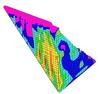
By means of a structural 3D model and the assumption of a RCC placement rate, stress and strain analyses were performed for the different stages and load conditions that affected the dam during the construction process and the operation phase. The design was adjusted based on analysis results through changes in some dimensions and in the RCC mixes zoning to obtain the desired security factors.
In the same way, the thermal and strain parameters, together with the calculated RCC placement rate, made it possible to calculate the evolution in the thermal stresses inside the dam body, and to perform the thermal cracking analysis. With the results of these analyses, the spacing between joints was determined to limit the maximum crack width to 1.3mm. The final adopted contraction joint separation was 18.5m. Before the initiation of the field works, all the RCC mixes were verified through field tests, in order to make the final adjustments to the aggregates proportioning and mix water content.
To simulate the increase in the material stiffness when the structure is subjected to instantaneous dynamic loads, the RCC strength characteristics were taken 50% higher when compared with dynamical stresses, following recommendations from tests and investigations carried out in previous similar projects.
Next, some average RCC mixes parameters are presented – density 2.53t/m3, Poisson ratio 0.23, friction angle 45°, strain capacity: 80µs, thermal diffusivity 0.00335m2/h, Thermal Expansion Coefficient: 7 x 10⁻⁶m/°C.
Grout enriched RCC mix
An enriched RCC mix was used in the first 40cm of the upstream dam face, in order to improve the structure watertightness, to avoid honeycomb formation in the downstream dam face, to enhance the support surface quality for the waterproof PVC membrane, and to facilitate the placement of the metallic steel shapes that fasten the membrane as well as the PVC seals in the contraction joints.
A slurry with a 0.8:1 water cement ratio and plasticiser additive (1% of cement weight) was applied to the layers of RCC 125 and 150kg/m3 mixes located on the upstream dam face surface, against the edge that is in contact with the reservoir. During the investigation process for the enriched RCC, satisfactory results were obtained with the 100kg/m3 mix.
The enriched RCC becomes, in practice, a conventional concrete that is consolidated with immersion vibrators and if necessary could be conventionally reinforced with steel bars. This material is strongly bonded to the RCC because both materials are part of the same placed and compacted layer.
The initial RCC mix tests (compression strength, tension strength, shear stress strength, elasticity modules, Poisson ratio) were carried out by the Materials Testing Laboratory of Los Andes University in Bogota, Colombia. With the data collected from these test results, the initial proportioning for the mixes and the basic material parameters required for the design were defined. This information was used for the first dam dimensioning.
The selected RCC mixes were tested and adjusted by the US Corp of Engineers Laboratory, in Oregon, US where all the parameters required for the structural, thermal, and cracking analysis were determined in a detailed way.
Compaction tests including simulation of RCC layer densification procedures, contraction joint construction processes as well as observations of the mix workability were done there. Tests to measure the maximum available time for the mixing, transport, placing, and compacting operations for the RCC mixes were also conducted.
Finally, when the definitive information about the materials (cement and aggregates) selected for the works was supplied by the contractor, a verification phase supported by the results of field tests performed in several laboratories especially arranged on the project site, was implemented. This stage was especially useful to adjust the optimal moisture content of the RCC mixes in order to ensure the workability without any reduction in the physical and mechanical properties.
With the final results obtained from the verification stage, new corrections in the RCC mix zonation of the dam were introduced. Again, the dam stresses and strains states were calculated to verify the completion with the adopted security factors.
During the entire dam construction process, a continuous technical control programme to ensure the quality of the RCC mixes was underway in order to guarantee achievement of the design standards.
Structural analysis
The dam structural design had the following objectives: to verify the geometry (slope of the upstream and downstream faces; to define the zonation of the RCC mixes inside the dam body; to determine the spacing between contraction joints; to calculate the stresses and strains for the different construction stages and design loads; to verify the adopted security factors and the convenience of the site where the dam would be located.
The structural analysis had several steps, according to the grade of detail available about the design parameters.
To calculate the effective stresses in the structure static, modal dynamic and time history structural analyses were applied to 2D and 3D FEM models, elaborated with specialised computer software (DAMSTAB, SAP-386,SAP-80, EAGD-84 and SAP-2000). The analysis considered usual, unusual and extraordinary load conditions. These load cases were according to the recommendations given by the US Bureau of Reclamation and also incorporated the concepts of the board of consultants of the owner and HMV.
The load combinations and adopted safety factors were:
• Usual load combinations: Static Analysis – Security Factor = 3 (defined as strength over acting stress, measured locally)
Reservoir in its normal operation level without overflow, structure self-weight, uplift pressures, maximum sediment height, minimum normal restitution level, thermal effects and construction earthquake (CE).
• Unusual load combinations: Static and modal dynamic analysis security factors =2
Reservoir in its maximum normal operation level with overflow, structure self-weight, uplift pressures, maximum sediment height, minimum normal restitution level, thermal effects and CE.
• Extraordinary load combinations: Modal dynamic analysis – Time History Dynamic Analysis were conducted for two cases:
Case 1: Security Factors =1.8
Reservoir in its maximum normal operation level with overflow, structure self-weight, uplift pressures, maximum sediment height, minimum normal restitution level, thermal effects after the end of the construction process, reservoir hydrodynamic effects in its maximum normal level, and design basic earthquake (DBE).
Case 2: Security Factors =1.0
Reservoir in its maximum normal operation level with overflow, structure self-weight, uplift pressures, maximum sediment height, minimum normal restitution level, thermal effects after the end of construction, reservoir hydrodynamic effects in its maximum normal level, and maximum credible earthquake (MCE).
The dynamical analysis for the load conditions described above, were done using several methods and models. Modal dynamic analysis on 2D and 3D models with and without joints were considered. Also, time history analyses for selected accelerograms were implemented for 3D models; a linear elastic analysis for the dam 3D model without contraction joints and a non-linear elastic analysis for the 3D model with contraction joints integrated.
The contraction joints were represented in the SAP-2000 computer models with the N-Link elements, that transmit totally the compression forces, partially the friction forces, and ignore the tension ones.
The basic assumptions for the seismic loads were defined from the seismic risk studies: For the CE an acceleration of 0.11g was adopted; For the DBE an acceleration of 0.22g was adopted; For the MCE an acceleration of 0.30g was adopted
For the time history analysis, three accelerograms were used: Taft earthquake (1952), El Centro earthquake (1940) and a signal obtained very near the project called Bocatoma, corresponding to the Armenia Earthquake (25 January 1999). Each one of these seismic records was scaled to the design acceleration depending on the considered load condition DBE or MCE.
Two thermal stress conditions were included in the structural calculations; the first, one year after the end of construction analysed with monolithic and contraction joints models and the other, 20 years after the completion of the dam construction, using the model that includes both the longitudinal joint and the transversal joints.
The following additional analysis were performed:
• Gravitational – Thermal analysis in the construction phase including five stages corresponding to the RCC mix horizontal zonation. Each step was simulated with a partial monolithic model that allows the analysis of the final stress state at the conclusion of each phase, and comparison of the results with the defined zonation.
• Incremental structural analysis for construction. This simulation incorporates the effects of the loads, material properties, and thermal stresses variations from beginning to end of the dam construction process.
The critical design parameter is the RCC traction strength to the tensile stresses generated in the dam body, when the structure is subjected to a seismic movement. The compression and shear stresses do not govern the structural behaviour.
Instrumentation
For great height dams and mainly when the standing limits are being exceeded, severe control of the design parameters and results is mandatory. A complete instrumentation system was designed to register and quantify the evolution of the temperature, stresses, strains, pore pressures, infiltration flow, and contraction joint displacements among other relevant factors included in the design. It was also useful to corroborate the correspondence between the real dam behaviour with the analytical predicted behaviour, and also to accumulate relevant information to be used in future projects.
To define the instrument type and location, foundation rock geotechnical properties, structure, construction methodology, structure height, maximum stresses and strains magnitude and distribution, temperatures evolution inside the dam body, estimated uplift, and pore pressures were taken into account.
Dam instrumentation included 39 electrical piezometers to measure the pore pressures inside the dam body; 25 electrical piezometers in the dam foundation, located at both sides of the grouting curtain; 18 additional electrical piezometers in the dam-rock contact surfaces and also inside inspection holes for the deep grouting; 334 thermocouples to register and quantify the temperatures evolution inside the dam body; 23 pressure gages to evaluate the stress in the three main orthogonal directions; 45 strain cells to quantify the unit strains inside the dam body; 127 joint displacement meters, to register the movement of the transversal and longitudinal joints.
These instruments were installed in six horizontal sections or instrumental levels inside the body of the dam.
There were also 22 landmarks to determine possible displacements of the structure by comparison with two reference landmarks installed on the firm rock. On the other hand, a set of discharge meters was installed in the drainage galleries to measure filtrations from the different dam elements, including the buttress.
During construction, a permanent monitoring of the instrument’s records was made. This job, together with the data obtained from the RCC quality assurance programme and from the grouting verification procedures, allowed a continuous analysis of the structure performance, to judge the measured information against the design hypothesis, and to improve the decision-making process.
Conclusions
1. Since the RCC dam construction alternative required less volume of quarry materials and generated less residues from the remaining quarry waste than the other alternatives considered, the environmental effects were minimised.
2. Mixes of RCC with medium to low cement content (between 150 and 85kg/m3) were successfully used.
3. The waterproofing with a PVC membrane on the dam’s upstream face is very effective, with measured infiltration flows smaller than 2 l/s in an area of 31,300m2. The connections between membrane strips were made by a thermal sealing method that allowed a fast placement rate. Although the joint systems between the PVC membrane and the plinth demonstrated good behaviour, they could be improved.
4. The RCC placement, membrane installation and construction of the spillway were made concurrently, speeding up the construction to meet the start of operation deadline.
5. Under the maximum design flood, water can pass over the entire dam crest length, meaning that in a critical situation the whole downstream face would act like a spillway.
6. The grout enriched RCC mix was successfully used to improve the water tightness and to facilitate the support for the PVC membrane.
7. With the adoption of 18.5m contraction joints spacing and with the longitudinal joint, an effective crack control was achieved.
8. The large quantity of tests performed before and during construction and the use of these results in the structural analysis allowed a more accurate RCC mix zoning for the dam.
9. The need to model the contraction and longitudinal joints was verified. The monolithic model performance (without joints) is completely different to the behaviour of the model with joints.
The latter is more adjusted to the results of the field instrumentation measurements.
10. A good representation of the contraction and longitudinal joints in the dynamic time history stress analysis was achieved by the use of connection elements available in SAP-2000 software, called N-Links.
11. Due to the excellent quality assurance procedures that included a huge amount of field tests, a complete structure instrumentation, and a continuous construction technical supervision, there is confidence in the adequate performance of the structure in the long-term.
12. A fast, reliable and economic construction method was implemented by means of an All Conveyor transport and distribution systems and a large capacity long range central Tower Crane.
13. The Joint inserter construction procedure made possible the construction of contraction joints without any interference in the RCC placing and compacting cycles.
14. The construction speed was optimised by the simultaneous execution of the following activities: contraction joints construction by means of the Joint Inserter method; spreading of bond mix between successive RCC lifts; use of the cement grout enriched RCC mixes;lacement of the required forms for the RCC lifts at the upstream and downstream faces; placement of the PVC membrane; collocation of the PVC seals inside the contraction joints; RCC zonation using two different types of mixes in each layer.
15. The previous record height for this kind of RCC structure has been successfully surpassed by 38%.
Related ArticlesSpotlight on...RCC Spotlight on... South AmericaTablesTable 1 Table 2