Seismic damage assesment at a coupled dam system using DCRs
3 April 2008Seismic damage assessment of arch dams, including dam-reservoir-foundations interaction oking seriously is examined using demand-capacity ratios obtained from linear analysis, and earthquake case studies show where further, nonlinear, studies would be required
Many studies have been done to determine the dynamic behaviour of arch dams. In the research, many theoretical and experimental studies have been presented: from how can be arch dams modelled to what kind of initial and boundary conditions can be used when analysing; from factors affecting seismic behaviour to examination of stochastic and deterministic linear and nonlinear analyses; from reservoir sediment effects to dam-reservoir-foundation interaction.
Reservoirs do have a considerable affect on the dynamic response of dams during earthquakes, and three approaches are used to consider such: the Westergaard, Euler and Lagrangian approaches.
In the Westergaard approach it is considered that a vibrated mass dispersion with the dam is similar to hydrodynamic dispersion towards the upstream face of the dam. In the Eulerian approach, the displacements are the variables in the structure and pressures the variables in the fluid. In the Lagrangian approach, however, the displacements are the variables in both the fluid and the structure. There is no need, therefore, for any extra interface equations in the Lagrangian approaches, and so compatibility and equilibrium are automatically satisfied at the nodes along the interfaces between fluid and structure.
Nonlinear procedures are required to asses the seismic damage level of concrete arch dams in earthquake-prone areas. However, it is generally known that nonlinear time history analysis of 3D arch dam-reservoir-foundation system demands too much memory and time on computers. It is also possible to use linear procedures for qualitative estimating of the damage level of concrete dams subjected to earthquakes[15-16].
This paper illustrates the application of linear time-history analysis for the earthquake response computations of an arch dam with the objective calculating the dynamic characteristics of the dam-reservoir-foundation system - i.e. dam displacement and stress response histories under horizontal component of earthquake motions. In addition, the paper examines the use of demand-capacity ratios to assess the seismic performance of the dam by Lagrangian approach.
Finite Element Formulation of Fluid and Fluid-Structure Systems
In the Lagrangian approach, fluid is assumed to be linearly elastic, inviscid and irrotational[17-18]. Rotational stress relationships are calculated the bulk modulus and the volumetric strains of the fluid, respectively. Rotations and constraint parameters are included in the stress-strain relationship.
In this study, the equations of motion of the fluid system were obtained using energy principles. Finite element (FE) approximation was employed to evaluate the total strain energy of the fluid system using a nodal displacement vector and the stiffness matrix of the system, respectively.
An important behaviour of fluid systems is the ability to displace without a change in volume, and for reservoir this movement is known as sloshing waves in which the displacement is vertical with an increase in the potential energy of the system due to the free surface motion.
The equations of motion of the fluid system have a similar form with those of the structure system when Lagrangian approach is considered in the formulations. To obtain the coupled equations of the fluid-structure system, the determination of the interface condition is required. Because the fluid is assumed to be inviscid, only the displacement in the normal direction to the interface is continuous at the interface of the system. Using the interface condition, the equations of motion of the coupled system to ground motion include damping effects.
Damage Criteria for Arch Dams
The earthquake performance of arch dams is evaluated in accordance with displacements, stresses, demand-capacity ratios (DCR) and the cumulative inelastic duration. DCR for arch dams is defined as the ratio of the calculated arch or cantilever stresses to tensile strength of the concrete used in the dam. The dam response to the maximum design earthquake is considered to be within the linear elastic range of behaviour with little or no possibility of damage if computed DCR values are less than or equal to 1.
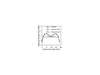
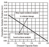
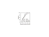
The dam is considered to exhibit nonlinear response in the form of opening and closing of contraction joints and cracking of the horizontal joints (lift lines) and concrete if the estimated DCR values exceed 1. The level of nonlinear response or opening and cracking of concrete is considered acceptable if the DCR value<2, the overstressed region is limited to 20% of the dam surface area, and the cumulative inelastic duration falls below the performance curve given in Fig. 1. The maximum permitted DCR for linear analysis of concrete dams is 2.
The cumulative inelastic duration in Fig. 1 refers to the total duration of all stress excursions beyond a certain level of DCR.
Seismic Damage Assessment of Arch Dams
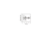
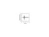
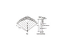
A double curvature Type-5 arch dam, which was suggested in ‘‘Arch Dams’’ symposium in England in 1968, is selected as a numerical example[23]. The geometric properties of Type-5 arch dam are given in Fig. 2.
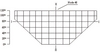
The height of dam selected is 120m and its computed thickness dam at the top and base are 5.35m and 23.35m, respectively. Type-5 arch dam is developed considering reservoir and foundation. Finite element model of downstream face of Type-5 arch dam, and sections and node selected for comparison of the results are given in Fig. 3.
There are three unknown displacements at each nodal point in dam, foundation and reservoir FE model, and there are 4355 nodes and 3188 finite elements used in modelling the coupled system - the dam, foundation and reservoir having 148 solid, 1560 solid and 1480 fluid finite elements, respectively. The ratio of Young’s modulus for the foundatio to the concrete is 0.643, and the foundation model is assumed to be massless rock and extends downstream for the equivalent of the heinght of the dam (H), 3H in the upstream direction and H to the right and left.
Reservoir model is developed by using fluid element and is extended as 3H. At the reservoir-dam and reservoir-foundation interface, length of coupling element is chosen as 0.001m. The main objective of the couplings are to hold equal the displacements between two reciprocal nodes. Element matrices are computed using the Gauss numerical integration technique[20]. The Newmark method is used in the solution of the equation of motions, and Rayleigh damping is considered in the analyses and damping ratio is selected as 5%. Linear analyses of coupled system are carried out by using ANSYS finite element program[24]. The material properties and element types used in the analysis are summarised in Table1.
Linear analyses are performed using three different ground motions - the earthquakes at Parkfield (1966), Imperial Valley (1940), and Mammoth Lakes (1980) - which were recorded. They were selected as they had approximately the same peak ground acceleration (PGA). The properties of the ground motions are given in Table 2. For reasons of computational memory needs, only the first 12 seconds of the ground motion time histories - but this is the most effective duration - is used in the analysis.
Displacements
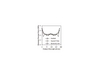
The variation of maximum horizontal displacements on the central cross-section (II-II in Fig.3) of the Type-5 arch dam, obtained from linear analyses for Parkfield, Imperial Valley, and Mammoth Lakes ground motions, are depicted in Fig. 4. The maximum displacements, obtained along the crest point and its values are 5.3cm, 6.6cm, and 7.8cm for Parkfield, Imperial Valley, and Mammoth Lakes earthquakes, respectively.
The variation of maximum horizontal displacements along the crest of arch dam for each ground motion are plotted in Fig. 5.
The time histories of horizontal displacements in upstream-downstream direction at the top, central FE nodal point on the downstream face of the crest (nodal point 48 in Fig.3) of the arch dam are plotted for each ground motion, in Fig. 6 (a-c). The time histories of the displacements shows similar variation with earthquake ground motions.
The contours of maximum displacements of dam-reservoir-foundation system for all earthquake ground motions are also be calaculated. The displacement contours represent the distribution of the peak values reached by the maximum displacement at each point within the section. Peak values of the displacements occur near the crest centre of the arch dam for all selected ground motions.
Principal Stresses
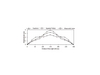
The variation of maximum and minimum principal stresses along length and height of the dam (I-I and II-II sections in Fig. 3) are plotted in Fig. 7 and Fig. 8 for each ground motion. The biggest values of the maximum and minimum principal stresses for Parkfield, Imperial Valley and Mammoth Lakes earthquakes are shown in Table 3. It can be seen from Fig. 7 that the maximum and minimum principal stresses obtained from Mammoth Lakes earthquake records along dam length at section I-I are generally bigger than those of Parkfield and Imperial Valley earthquake records. However, maximum principal stresses obtained from Parkfield earthquake record near the crest at section II-II are bigger than those of the other two earthquakes.
The contours of maximum principal stress of dam-reservoir-foundation system for all earthquake ground motions are also calculated. These principal stress contours represent the distribution of the peak values reached by the maximum principal stress at each point within the section. Maximum principal stresses, which are maximum tensile stress, generally occur near the crest level.
Demand-Capacity Ratios
The time histories of maximum principal stresses (tensile stress) at nodal point 48, which is the most representative crest point of downstream side of the dam, for each ground motion are plotted by displaying the demand-capacity ratios (DCR) in Fig. 9 (a-c). If the size effect is considered, the tensile strength of mass concrete in relatively thick arch-gravity dams drops to below 3 to 4MPa[26]. In this study, tensile strength of concrete material is selected as 3 MPa. It is clear from Fig. 9 that some values of maximum principal stresses are over than DCR=1 for all ground motions. It means that the maximum principal stresses that occurred on the dam are much more than tensile strength of concrete used in dam body.
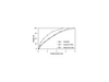
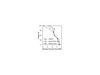
The performance curves at nodal point 48 of the arch dam are presented in Fig. 10 for each ground motion. The level of nonlinear response or opening construction joints and/or cracking of concrete is considered acceptable if the DCR value<2[16].
The results shows that DCRs for Imperial Valley and Mammoth Lakes earthquake records are less than 2 and the cumulative inelastic durations at all DCRs almost falls below the acceptance curve. It can be stated that the linear analyses of dam-reservoir-foundation system is sufficient for Imperial Valley and Mammoth Lakes earthquake records and no or little damage may occur on the dam body.
However, the DCRs from Parkfield earthquake record exceed 2 and the cumulative inelastic duration is substantially greater than the acceptable level. It is thought that Parkfield earthquake record would cause significant damage on the dam body. Therefore, nonlinear analysis of the coupled system under Parkfield earthquake record would be required for more accurate estimate of the damage.
It can be generally stated, therefore, that earthquake ground motions which have approximately same PGA can be demonstrated to experience different damage levels. Therefore, DCRs should be determined for different earthquake records before making a decision on the controlling and designing of existing and new arch dams.
Author Info:
Bayraktar, A. Karadeniz Technical University, Department of Civil Engineering, 61080, Trabzon, TURKEY
Sev, B.M. Karadeniz Technical University, Department of Civil Engineering, 61080, Trabzon, TURKEY
Calayir, Y. Firat University, Department of Civil Engineering, Elazi, TURKEY
Akkose, M. Karadeniz Technical University, Department of Civil Engineering, 61080, Trabzon, TURKEY
Contact: Alemdar BAYRAKTAR, Professor.
Tel : + 90 462 377 26 53
Fax : + 90 462 377 26 06
E-mail : alemdar@ktu.edu.tr
TablesTable 3 Table 2 Table 1