China
Siltation
Silt-proof measures
27 January 2004Following analysis of data measured out of Baishakou tidal power station, measures were proposed to control sediment in the reservoir
BAISHAKOU tidal power station in China was put into operation on 1 August 1978 when the first two generators were commissioned. In 1987 another two generators went into operation, followed by a further two in 1987.
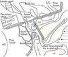
Baishakou, which has an annual output of 2,320,000kWh, is located 20km away from the southeast of Rushan County, Shandong Peninsula. The reservoir, named Baishakou lagoon, covers an area of 3.2km2 and connects with the Baishakou gulf. The northern coast is home to a 3.5km long and 1km wide sand dam, which connects with the eastern sand-proof embankment for 8km, extending to the Yandunxia corner. There is a reef coast in the west, with folded lines, (See Fig. 1).
The lagoon is shallow, with a smooth and wide bottom. The reservoir capacity is 2,040,000m3 during spring tide period, 1,550,000m3 during middle tide period and 1,030,000m3 during neap tide period. In the southwest of the lagoon, there is a mouth-gate which is 500m wide, and where there are three pivotal projects: the dam, the water inlet gate and the power station. The dam is at the mouth of the main flow; the water inlet gate and the power station are located at the western side of the dam. The power station buildings, which house six 160kW shaft tubular generators are located to the west of water inlet gate. The buildings are semi-enclosed, with inside walls of concrete impervious barrier 30cm thick, to prevent them from being inundated during neap tide period.
Water and Sand
The reservoir area of the power station is mutually affected by runoff and tide. The silt sand in the reservoir area comes from the following two sources:
Sand from drainage area
Baishatan river is upstream of the Baishakou lagoon. With its full length over 10km it controls the drainage area of 54km2. The geology in the drainage area belongs to the Pre-Siniax stratum; the rocks are mainly made of granite with serious weathering and a thick weathering layer. This drainage area belongs to the monsoon climate area, with precipitation being very rich. During the flood period, the resulting rainstorms and floods carry a great amount of sand, almost all silts in the lagoon (See Table 1).
Water and sand from the sea area
When analysing the data of bed silt gradation in the sea area out of the lagoon mouth-gate of the station, D=0.05mm (diameter of sand grain) is the boundary between sand from the drainage area and sand from the sea. There is no sand grain with D‹0.05mm in the silt in the sea area out of the mouth-gate. The sand grain with D›0.05mm contains 87% of total deposition quantity in the reservoir. Parts of the sand from the sea-bed flow to the reservoir area along with the tide, when spring tide occurs out of the mouth-gate. According to the sand gradation and silt deposition quantity 120m away from the dam, sand from the sea area contains about 13% of the total silt deposition quantity.
Influenced by topography and landforms, in addition to the coordinated effect of wave and tide in the sea, the evolving regularity of silt in the sea area out of mouth-gate is very complicated. The silt comes from the following:
Sand carriage from sea bed
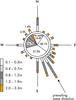
The most important motive power for sand movement in the sea area is sea wave. In the summer, the power station is affected by wind and wave from the southeast, mostly by swell, with large wave-height, most of which is toward–bank wave. In the winter, mostly by storm, the direction of wave is dispersive. The wave graduation and direction are shown in the Sea Wave Rose (Fig. 2). The toward-bank wave prevails in Fig.2, and the wave-height is over 0.7m a fifth of the year. The maximum velocity created by the 0.7m wave-height is 68cm/sec in the sea bed of 4m deep, where sand grain diameter is 0.068mm. The starting velocity of the sand grain is 20cm/sec, thus sand in the sea bed is lifted and carried toward the coast.
Sand movement along the coast
When sea wave moves to the coast and is broken, the wave energy is divided into two vectors, the vertical and the parallel. The vertical vector makes the sand move to the shore from the sea bed; the parallel one makes the sand along the shore move from the east to west, silting dunes near the mouth-gate.
Sand silt
From 1972 to April 1984, the silt moved into the reservoir area was 2,570,000m3 – about 87% of the total silt – which is the main source of silt in this reservoir.
Serious silt in the front sea area is the most worrying. As the previous dynamic equilibrium was destroyed following the construction of a dam in the eastern coast, sand carriage amount caused by wave, both in the sea bed and along the coast, moves to the generation tailwater channel, (See Table 2).
On the other hand, we know that the storm tide has a great effect on sand silt in the generation tailwater channel. Nowadays however, the lower part of the generation tailwater channel has become a smaller water-passing section, which holds back its function.
As a result, four designs have been developed to analyse the economical benefit of digging sand in the generation tailwater channel to reduce the difference in water level between the outer sea and tailwater. The first design with the digging amount of 3000m3 was found to be the most beneficial.
Synthetical measures to prevent silt
Sand silt in the reservoir area comes mainly from Baishatan river, therefore, the finished course-changing project of the river needs to be continuously improved. This means a floodgate should be built at the new entrance so that the sand flows to the sea.
Reservoir Maintenance
Five crayfish ponds have been built in the reservoir area without permission, aggressing 398,000m3, occupying 12.7% of the reservoir capacity. Measures must be taken to prevent the ponds from being built; otherwise the reservoir area would be deposited.
Ageing-prevention
The natural development of Baishakou lagoon is similar to most other lagoons: lagoon–swamp–damp land–land. In recent years, the eastern part of the lagoon has begun to age. Helophyte grows very quickly. The reed marsh area expands and the saline concentration reduces year by year. To keep the generation benefit and prevent the lagoon from aging, 2.4.2 Clorobenzene Oxygen Acetic Acid or Na State of Pemnla Chlore Phenoe is sprayed. This will inflict heavy casualties on monocotyls and dicotyls. Once sprayed, helophyte will die out at its root and will not grow within three years. The spray is harmless to humans and marine animals, and is cost effective.
Silt-prevention in Tailwater Channel out of the mouth-gate
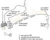
The silt dune out of the mouth-gate of Baishakou power station directly affects the water-flow into or out of the station (See Fig. 3). When water comes into the reservoir during tide rising period, it is obstructed by the sand dune and 2500m3 of sand is carried into the reservoir annually.
The silt outside the mouth-gate near the sea area is determined by the water quantity swelling from the seaport and sand quantity (including stormy tide). If this is equal to the amount of water and sand from the ebb-tide and generation tailwater during the same period, we have the following two equations:

(1)

(2)
In equations 1 and 2 during the tide period T, W is the total amount of water drained out. Ws is the total amount of silt. B, H, U in turn means, at time t, the water-level width, the water depth, and the ebb velocity at tide level. B, H, U means the average of B, H and U during the research period T (the total ebb time period). S is the silt discharge. So is the average silt discharge during the period T at ebb time. S can be defined by the following formula:

(3)
Uos is the stopping current velocity of the sea bed silt; it can be defined by the following:

(4)
In equations 3 and 4, g: acceleration due to gravity, _s: specific gravity of sand particles in the sea bed (in Baishakou _ s=1.2~1.3). D: sand grain diameter. _: specific gravity of sea water. K: decided by the normal distributing formula of current velocity. Supposing Q is the average ebb current capacity during the research period T of Baishakou tidal power station, and solving Equation 1, Equation 2 and Equation 3 simultaneously, we have:

(5)
The main power force factors for sand silt are storm tide and southeastern waves. The swell coefficient b is decided by degree of the swell.

(6)
?H: the average tidal difference during swell section. H: the average sea depth at medium tidal level. Because of the relative active force, many are used as indexes to express the degree of the sea area deposition, such as the ebb current velocity, current velocity of generation tailwater channel, and the width-depth ratio of the sea area out of the mouth-gate. Therefore, the comprehensive indexes in the sea area can be expressed by the following variable:

(7)
In equation 7, a: the seashore stability coefficient. Because of the fine sand of the sea bed out of the mouth-gate of the Baishakou area, and the fine earth of the shore, the available fine sand is 0.9~1.1; the available fine earth is 0.8~1.0. According to the data of tide river mouths worldwide, b=0.15. If the sand silt is on balance out of the mouth-gate of the tidal power station, we have: ?Kn/?U=0
On the basis of the above mentioned deduction, calculations were undertaken. The scouring force of generation tailwater and the ebb current velocity can not scour up the silt amount moved by the sand to the shore and mouth-gate tailwater tunnel during the stormy tide period (meteorological seismic sea wave), especially when there is strong wind. For example, in July 1973 and September 1985, the meteorological seismic sea wave caused by hurricanes reached 2.66m, net silt amount was 7000m3, and a dune across the mouth-gate occurred.
Therefore, to control silt effectively and keep the main channel of generation tailwater clear, engineering facilities, mechanical method of cleaning silt and biological environmental protection must be coordinated.
Mechanical Sand-proof Methods
This kind of experiment has been undertaken many times. For example, using mud-digging ships will not result in silt ejection because the tube of ejecting silt cannot swerve. In addition, the sand-proof test of firing pump is not successful.
However, the use of small tugs with mechanical harrow, single-hydraulic giants and scattered-hydraulic giants to disturb and dredge silt, has proved successful. Most of silt can be taken into the sea during the tide and generation tailwater.
Engineering Facilities
Two designs at the tidal power station have led to increased deposits of silt. Firstly, the arrangement of the eastern sand-proof dam doesn’t accord with the general principle of sea bank engineering management: ‘making the best use of all sorts of destroying force in nature and reducing the destroying force per bank-line to the minimum to control the sea bank effectively and lower the coast”’. Secondly, the western sand-proof dam, 80m long, should not have been built. It is necessary to demolish the western dam, but unfortunately this is not acceptable as it is a good fishing vessel wharf. To combat this, the eastern dam needs to be extended. According to data obtained from models of harbor and wharf seabank engineering, and from engineering work undertaken in the field, the eastern dam is a spur dam, and the intersection angler between the dam axle and the prevailing wave direction 149° in the area should be 100°-110°. Therefore to extend the existing eastern dam, turning 30° to the south is surely necessary. With its length L=0.5 BW (BW is the distance from water edge to the broken wave-pot), a hook-like dam is built, this not only avoids the occurance of shirting current caused by the spur dam head which brings sediment into tailwater channel, but also prevents sand from being carried along the bank to tailwater channel by the 115°-150° sea wave.
The scoring sluice with fifteen holes was built in 1984, and five scouring experiments have been undertaken in the tailwater channel, proving that a better result could be obtained only at the water-level of astronomical high tide. In an experiment in June 1986, when the scouring sluice water-inlet sluice, ship sluice and station units were all open, 3000m3 of sediment in the tailwater channel was rushed out. This facility ensures that the main course of the tailwater channel (50m wide) passes unimpeded in normal years. This should be coordinated with mechanical measures after typhoon or stormy wave.
Biological Measures
Aiming at the silt characteristic out of the mouth-gate of the power station, biological measures should be taken, coordinating with engineering facilities. A large area of plants was planed on the sand dam. For different levels, three parts are divided: high, middle and low. On the 1-2m low beach and the dam field, spartina anglica is planted; this kind of plant is flood-resisting, salt-resisting, and fast-growing. On the 2.5m middle beach (the supposed level is 1.55m), reed is planted. On the high beach, locust trees are planted.
At the same time, west to the sea entrance of the newly-built Baishakou river route mouth, a short hook-like dam has been built as a barrier. Spartina anglica in the low beach and dam fields not only prevents sediment from being washed away by wave and wind, but also provides feed for cow and sheep, and bait for fish. It also accelerates the growing period of reed in the middle beach, which is used as building materials and fuel, and forms a green scenery together with the dense locust trees on the high beach. This will provide living space for birds, a base for marine animals to breed, and will also act as a summer resort.
Such kind of engineering facilities and environmental protection coordinate to obstruct the sediment of Baishatan river at the sea entrance of the new river route. The sediment is unable to move toward the mouth-gate from east to west, and is silted away from the power station. This will extend the service life of the power station without influencing the unimpeding of the generation tailwater channel and tailwater filling the reservoir.
TablesTable 1 Table 2