The X factor
18 July 2006The X-Blade runner technology has been designed to provide improved stability over large ranges in flow and head, as well as strong cavitation behaviour and higher efficiency levels
First developed during the early stages of China’s Three Gorges project, GE Energy’s X-Blade runner design for Francis hydro turbines has now been patented and is being implemented in other projects throughout the world.
The latest example of the use of this technology is at Tacoma Power’s Mossyrock hydro power station on the Cowlitz river in Lewis county, Washington state, US. Expected to be completed in 2009, the project is designed to provide higher efficiency, a greater range of stable operation, and reduced maintenance costs for the hydro plant.
The upgraded units at Mossyrock are expected to each have unique performance curves, enabling them to more efficiently cover the full operating range of the plant. The desired result will be increased energy production for Tacoma Power.
According to Max Emrick, assistant general manager of production engineering for Tacoma Power, GE’s proposal featuring its X- Blade technology met the utility’s project requirements: higher efficiency, less cavitation and an expanded operating range.
The new technology is also being applied for the upgrade of the New Melones hydroelectric plant on the Stanislaus river near Sonora, California. X-Blade runners are being installed to increase the efficiency of two Francis turbines at the site.
Head range of 300 to 580 feet (91.4m to 176.8m) at the New Melones plant is much larger than at most hydro sites in the US, according to Robert Balletti, a regional manager for GE Energy’s hydro business. ‘This project represents exactly the type of challenge our X-Blade technology was designed for,’ he says. The X-Blade design also has been implemented at the Cougar upgrade project, a US Army Corps of Engineers (USACE) site in Oregon.
X-blade design and development
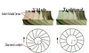
Using Computational Fluid Dynamics (CFD) and extensive model testing, GE developed the X-Blade design over several years. The original design was based on years of experience accumulated by technology that GE acquired in 1999. During the development process, the hydraulic advantages of the X-Blade design (stability over large ranges in flow and head, good cavitation resistance and low pressure pulsation levels) were fully confirmed, and major improvements were recorded. The runner design is characterised by a special blade geometry. Figure 1 compares the design with a conventional Francis runner, showing the inlet blade lean and the skewed outlet that are typical identification marks of the X-Blade design.
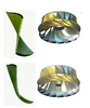
Figure 2 offers a comparison of blade geometry for medium head runners. This clearly shows the significant difference in blade shapes and also illustrates the reason for the name, ‘X-Blade’. In addition to the hydraulic advantages, the less curved and less complicated shape of the X-Blade is designed to offer production advantages.
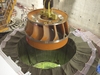
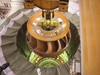
Figure 3 shows an X-Blade runner for the Three Gorges project on the Yangtze river in China. The units for this project are the world’s largest Francis turbines.
Performance features
The primary attribute of the X-Blade designs relate to the uniform flow distribution in the runner. High-flow velocity along the band is a typical problem with Francis runner design. Such high velocity creates low-pressure zones, which can lead to cavitation and secondary flow problems. Francis turbines often suffer from inlet cavitation erosion on the suction side nearby band, low efficiency and hydraulic instability because of an unbalanced inlet pressure distribution, which cannot be completely avoided with the traditional runner design – especially on units operating in a large range of net heads.
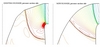
Figure 4 compares CFD for an existing and a proposed new runner for the same turbine. The existing runner shows a typical low-pressure zone just behind the inlet at the band, which was the reason for heavy cavitation on the prototype. The new X-Blade runner shows uniform pressure from band to hub with no low-pressure zones or cavitation problems. Model tests on both designs fully confirmed the superior performance of the X- Blade on cavitation performance, as well as efficiency, hydraulic stability and pressure pulsation level.
Efficiency
In recent years, the introduction of CFD has enabled a major improvement in Francis turbine efficiency – the maximum efficiency of the X-Blade runner is higher than modern runners based on traditional geometry. In addition, the X-Blade runner maintains high efficiency when operating off-design. This ability is especially noteworthy when the runner is operating through a large range of net heads.
Blade loading and cavitation resistance
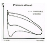
Figure 5 shows pressure distribution on the suction and pressure side of the runner blade, close to the band. The X-Blade shows smaller pressure differences between pressure and suction nearby inlets. Typically, the traditional runner shows a low-pressure zone on the suction side behind the inlet with cavitation risk, as also clearly indicated in Figure 4. Comparing runner geometry, it is typical that the X-Blade runner blade is shorter along the band. The traditionally designed runner will normally need to be extended into the draft tube, which is an indication of the problems with higher flow and unfavourable blade loading along the band.
Hydraulic stability
All Francis turbine runners, when operating off-design, will eventually show phenomena like interblade vortices, inlet cavitation or draft tube pressure pulsations. Because of its uniform flow and pressure distribution, the X-Blade runner can operate in a larger range of flow and heads before such phenomena occur or become critical.
The skewed outlet geometry with the relatively small outlet diameter at the crown contributes to the typical low draft tube pressure pulsation level, which has been verified on various models and prototypes. The X-Blade model shows a much smaller and less intensive vortex in the draft tube centre than other runners. Therefore, if air admission to the draft tube is required, the turbine with the X-Blade runner needs only a small amount of natural air admission through the runner cone.
Sand erosion resistance
Sand erosion is closely linked to the water velocity. Another plus, according to its manufacturers, is that the X-Blade runner, having fewer local zones with increased velocity, fewer problems with secondary flow and no whirls behind the inlet edge, is more resistant to sand erosion compared to traditionally designed runners.
Upgrading turbines
Besides demonstrating high efficiency and a low level of pressure pulsations, the X-Blade design is especially resistant to inlet cavitation and stability problems due to large head variations. Thanks to these features, the technology is being successfully used to upgrade existing turbines in projects around the world.
Author Info:
Jan Tore Billdal, Technical leader, Ph.D, GE Energy (Norway) AS, Gåsevikveien 6, P O Box 125, N-2027 Kjeller, Norway. Tel: +47 64 84 39 59. Fax: +47 64 84 39 01. Email: jan.billdal@ps.ge.com. www.gehydro.com