Tidal turbine development
9 January 2007Several important aspects of the development of bulb-type turbine generator-units for Sihwa Tidal, the world's largest tidal power plant, are described in this paper. Although the units' layout is based on that of conventional run-of-river plants, their installation in a maritime environment adds substantial complexity in terms of corrosion protection to the project
In an effort to diversify the country's energy supply, the Korean Water Resource Corporation (K-Water) decided to build the world's largest tidal power plant at Lake Sihwa. The site is located in the Midwest of the Korean Peninsula in the Gyeonggi province, close to Seoul. Lake Sihwa is an artificial water body created in 1994 by the construction of a dam to reclaim land and to secure irrigation water for the region. The area of the lake is 57km2 with a volume of 330Mm3 and has to be kept at a maximum level of -1m.
However, due to population growth and rapid industrialisation, the water quality of Lake Sihwa deteriorated immediately after its construction. Therefore, different schemes for the re-establishment of a water exchange between the reservoir and the sea were assessed, out of which the implementation of a tidal power plant was deemed to be the most promising. Beside an annual production of 543GWh of electric energy, the plant will improve the water quality of the lake by the circulation of 60B tons of seawater per year. The working principle is flood generation, i.e. the turbine-generator units work in the direction from sea to the lake. During ebb, the turbines support the water exchange through the dam gates by turning reversely in sluicing mode.
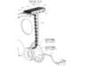
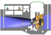
The plant comprises 10 turbine-generator sets with a total of 260MW, designed for a rated head of 5.82m. The runner diameter of the turbine is 7.5m and its rated speed is 64.29rpm. The generator stator has an outer diameter of 8m. With a stator voltage of 10.2kV and a load factor of 0.95, the apparent power of a single generator amounts to 26.76MVA.
va-tech Hydro (now andritz VA Tech Hydro) is a sub-contractor of Daewoo Construction & Engineering, who is the leader of the Korean joint venture acting as the main contractor for the erection of Sihwa Tidal. The scope of VA Tech Hydro comprises the detail design of the turbine-generator units and their ancillaries. Moreover, VA Tech Hydro will supply the core components for turbines and generators. The plant is scheduled to be operational in 2009.
Turbine engineering issues and corrosion protection
The design of the electro-mechanical equipment for tidal power plants implicates a lot of technical challenges. Not only the fact that there are ten large bulb units to deliver within the project's very ambitious time schedule, but also hydraulic optimisation and corrosion protection engineering play a major role for the success of this project.
The general design concept is based on conventional run-of-river bulb units, but there are some technical highlights that have to be considered, e.g. the capability to operate in reverse mode when emptying the basin and an increased number of operating cycles with two starts and stops every day.
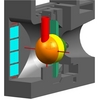
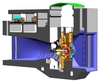
Special attention has to be paid to corrosion protection to avoid problems with the electro-mechanical equipment operating in seawater. A combination of passive protection measures – with the appropriate selection of materials and coatings – and active measures, such as the installation of a cathodic protection system, have to be made to guarantee a long life time and high availability. Especially in the field of the selection of materials, the units will differ from conventional hydro-electric power plants. For several components usually made of carbon steel at run-of-river units, stainless steel will be used instead, such as the runner hub, runner cone, wicket gates, gate barrel cones and shaft seals. Special care has to be taken in areas which cannot be protected sufficiently by the Cathodic Protection System e.g.: overlay welding, stainless steel quality with higher resistance against sea-water corrosion. Painting material resistant to sea water will be used for all sea water contacted surfaces of carbon steel components.
Special steels with increased molybdenum content will be used for core components, critical areas will be clad-welded with seawater resistant alloys and a cathodic corrosion protection system will protect stainless steel parts and coated carbon steel structures against corrosion by a potential shift into the cathodic region. The necessary protective current depends on the oxygen content of the electrolyte (sea- or brackwater), the salt content, the alkalizination of the protected surfaces, the temperature and, to a great extent the flow velocity, has to be adapted continuously. Because assembly has to be carried out in a sea water environment, special precautions will be necessary.
Hydraulic layout
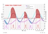
The optimization of the hydraulic layout was driven by the idea that the available basin volume had to be filled within a given time with a maximised energy production. That means that units need to be operated at very high efficiency levels under varying heads during the whole filling cycle. Other relevant aspects for conventional run-of-river plants, such as the ability for water level regulation or frequency control, are of less importance.
To optimize annual energy production, the gross head for the start of power generation of each cycle is of high importance and was subject to detailed hydraulic studies. If the start is too early, the basin is filled with low head difference between the sea and the basin but for a longer generation time. If the start is too late, heads are higher – which means that the water discharged into the basin can produce more energy – but generation time might become too short. Large numerical models have been developed for the optimisation of annual energy production within the given circumstances at Sihwa.
Generator Issues
Corrosion Protection
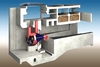
Besides the formidable tasks encountered in hydraulic and structural engineering, generator design was also demanding. The most pertinent fact of this project is that all external surfaces of the turbine-generator unit are in contact with sea water. This means that joints between different parts of the bulb need to be extremely resilient against crevice corrosion. It is a well known fact that the working principle of cathodic corrosion protection and sacrificial anodes is the modification of electric potential on the surface of a conducting body. Electric potentials, however, do not penetrate well into narrow gaps between joint structural elements leaving these unprotected against corrosive attack. The obvious remedy against this crevice corrosion is the use of extremely corrosion resistant materials in the vicinity of the gaps.
Although the inner of the bulb is not in direct contact with sea water, the atmosphere contained within might be loaded with slight amounts of salt thus creating corrosive films together with condensed humidity. This could be detrimental to all uncoated parts of the stator package but also to the winding of the generator, which is on high voltage potential. Sufficiently conducting films on the surface of the stator bars might pose the threat of surface discharges.
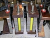
Similar considerations are true for the assembly process of the stator package. During this process, all uncoated parts exposed to a salt-laden atmosphere might suffer from corrosive attack. These parts, such as the stator slots, have to be covered by a suitable coating. In the case of stator slots, this coating has to be semi-conducting for properly grounding the outer corona protection of the bars and preventing short-circuits between adjacent stator sheets. Another sensitive part within the generator is the brush gear. Due to the fact that the field winding is without current in sluicing mode, the brushes have to be lifted during periods of sluicing operation. Otherwise, any patina on the slip rings would be destroyed within a short time.
Cooling
The cooling of the generator is partly done by direct contact of the stator lamination with the inner side of the generator housing and heat conduction towards seawater. The major part of the losses, however, is extracted from the generator by air-water coolers. Consequently, the cooling water has to be re-cooled by sea water via external heat exchangers. In order to secure high heat transmission rates and low fouling, these external coolers are plated with stainless steel. As a consequence, any combination of materials with different electrochemical activity might create problems if the design is not carried out properly.
Calculations
Of course, detailed structural and electromagnetic calculations were carried out in order to insure the proper functioning of the generator under the most adverse conditions of frequent starts and stops and unsteady thermal behaviour.
Author Info:
The authors are: Dipl.-Ing. Markus Schneeberger, Ing. Leopold Losbichler, Ing. Johannes Jagersberger, Dipl.-Ing. Georg Thaler, Dipl.-Ing. Walter Harb, and Dipl.-Inform. Dipl.-Ing. Dr. Erwin Schlemmer, MBA. VA Tech Hydro GmbH. For more information, email: Markus.Schneeberger@vatech-hydro.at
This paper is based on a presentation at the 14th International Seminar on Hydropower Plants, held from 22-24 November 2006. For further information on this event, contact Dr Eduard Doujak, Email: edoujak@pop.tuwien.ac.at.