Tunnelling at Bogong
12 June 2009Bogong power station in Australia was always envisaged as part of the Kiewa Valley hydroelectric development in Victoria, but it was never built. However project owner AGL recognised that completion of this scheme addressed future peaking and renewable energy requirements in the state, without the need for a new dam. Paul Thomas of McConnell Dowell highlights the tunnelling components of Australia’s largest hydro power project for 25 years
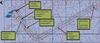
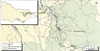
The Bogong power development project is situated within the Alpine National Park in the state of Victoria, Australia. Bogong village is approximately 380km northeast of Melbourne. The east Kiewa river flows adjacent to Bogong village, and this is the location of the construction and eventual commercial operation of the power development project.
The Bogong project is designed and positioned to be integrated with the existing power generating facilities forming the Kiewa valley hydroelectric scheme.
The project will in essence be the ‘final link’ in the scheme. Construction of the existing Kiewa hydro scheme began in the late 1930s and was completed in 1961, with World War II temporarily affecting construction works.
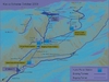
The current scheme basically consists of:
• a) Main operational control centre, terminal substation and regulating pond located in Mount Beauty, with intakes from both the west and east Kiewa rivers.
• b) Existing west Kiewa power station that has a generation capacity of 62MW. Supplied via the existing headrace tunnel and lower west Kiewa diversion.
• c) Clover power station that has a generation capacity of 29MW and located downstream of Junction dam along the east Kiewa river.
• d) Lake Guy/Junction dam, head storage for Clover power station.
• e) Bogong Creek Raceline, existing tunnel.
• f) Location of Bogong power development project (2x70MW) currently under construction.
• g) Existing tunnel (pressure pipeline) feeding McKay Creek power station.
• h) Mckay Creek power station generation capacity of 150MW provided for by a Pelton turbine.
• i) Rocky valley reservoir, main reservoir.
The basic operating principle of the Kiewa hydro scheme is to divert and harness the two branches that feed the east Kiewa river, namely the Pretty Valley branch and Rocky Valley branch, as well as the west Kiewa river. Approximately 310m2 of the Kiewa river catchment is utilised, in addition to 32km of water transfer infrastructure (aqueducts) from adjacent catchments with the majority water coming from snow melt during the winter season.
Rocky Valley reservoir is the main storage for the Kiewa scheme which can hold 28,000M litres of water. The Pretty Valley reservoir, at an altitude of 1600m, is the highest storage dam for hydroelectric generation in Australia. The water flows from this reservoir via a diversion dam into the Rocky Valley branch into Junction dam and through a series of tunnels and surface pipelines to McKay Creek power station. The subsequent flow of water through the stations at lower levels allows water to be reused to generate electricity prior to final discharge into the Kiewa river from the regulating pond located at Mount Beauty.
Design features
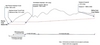
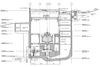
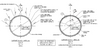
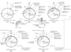
The viability of the Bogong project was first investigated by AGL Southern Hydro in 2000. AGL subsequently engaged GHD and SKM to develop a concept design. The main elements of the project are summarised below and detailed in Figures 1 and 2 (Note: Actual depths and gradients are indicative and do not reflect the final scheme). The main structural elements of the project are:
• Power station.
• High pressure headrace tunnel.
• Downstream dropshaft.
• Headrace access tunnel.
• Main headrace tunnel.
• Headpond dropshaft.
• Headpond.
Hydraulic data
The proposed Bogong power station flow capacity was required to match the discharge from McKay Creek station. This basically equated to the minimum flow at Rocky Valley reservoir to produce 150MW at McKay Creek of 37m3/sec at Full Supply Level (FSL) and 39m3/sec at Minimum Operating Level (MOL).
The uncertainties surrounding the above values concluded, at concept design stage, that Bogong needs to be capable of 40m3/sec. The head contract further specified the range of water levels. These levels are summarised in Table 1.
Waterway diameters
A preliminary head loss assessment for a range of tunnels and liners was undertaken to determine optimum diameters. The head loss was determined for a flow of 38m3/sec which would reflect normal maximum station flow. The waterway diameters determined during the concept design were based on evaluations of construction requirements and proposed methods of excavation.
The diameter ranges considered are summarised below:
• Headpond dropshaft 4m~7m diameter.
• Main headrace tunnel 4m~6m diameter.
• Downstream dropshaft 4m~6m diameter.
Contract award
Tenders were called by AGL Southern Hydro in early 2006. The contract was awarded to McConnell Dowell Constructors (Aust) in September 2006. The conditions of the contract are based on using elements of the FIDIC Conditions of Contract for Plant and Design – Build, First Edition 1999. The awarded contract sum was for A$158,710,001.69. The scope of the contract works covered:
• The design and construction and lining of a tunnel connecting the McKay Creek power station with the proposed Bogong power station.
• The design and construction of all permanent and temporary civil works associated with power station infrastructure, including roads, site facilities and revegetation.
McConnell Dowell Constructors subsequently appointed Halcrow Pacific as the designer for the works. The contractual timeframe for the works is 21 September 2006 to 20 December 2009.
Having engaged Halcrow Pacific in October 2006, McConnell Dowell and Halcrow commenced detailed construction design for both the permanent and temporary works. The original design programme provided by Halcrow showed the entire design scope being completed by late September 2007. At the time of preparing this article the design phase is still ongoing optimisation and refinement with an estimated 97% of the design scope completed.
McConnell Dowell was required under the head contract to guarantee the required rated discharge scheme of 38m?/sec (19m?/sec to each unit) and to confirm the guaranteed minimum head loss which was determined to be 18.689m, with a total estimated head loss of 15.985m. In order to derive the head loss, certain assumptions were made during tender on construction methods, such as excavation and liner types that would account for frictional losses. These are summarised in Table 2.
Power station structure
The power station structure will eventually house two vertical shaft Francis turbine generating sets. Under a developed gross head of 426m, each set will have a nominal rated output of 70MW. The power station output will be connected to an existing 220kV transmission line located adjacent to the power station at Bogong village. This connection is facilitated through unitised indoor generator step-up transformers, indoor gas-insulated switchgear and a single circuit 220kV underground XLPE cable connection. The existing transmission line conveys the output of McKay Creek power station through to the Mount Beauty terminal sub-station.
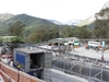
From a functional perspective, the power station will provide a secure and water tight structure to accommodate all the hydroelectric plant in addition to ventilation and visitors galleries. The final power station structure will be almost entirely buried to ensure minimal visual impact to the environment.
High pressure headrace tunnel
The concept design developed a complete steel liner of 3.4m dia ID for the entire 1200m of the high pressure headrace tunnel. The steel liner wall thickness ranged from 34mm~40mm. The necessity to provide the steel liner was to prevent hydraulic jacking or fracturing of the adjacent rock whenever the internal water pressure exceeds the minimum principal stress in the rock.
The head contract required the contractor to undertake a series of hydrojacking tests with the design objectives of: (i) Minimising the length of the steel liner; (ii) Positioning the downstream dropshaft to minimise the length of the steel liner; (iii) Determine the permanent lining requirements in the main headrace tunnel at the location where the ratio of available cover to required cover is a minimum.
Through value engineering McConnell Dowell was able to reduce the ID of the steel liner from 3.4m dia to 3.0m dia without compromising the hydraulic requirements. This resulted in significant cost savings for AGL. Further optimisation of the steel liner length was achieved following in-situ over coring and hydro-jacking tests.
Main headrace tunnel
As the Bogong Power Development is being constructed within the Alpine National Park and to ensure no surface impact within the park during construction, the concept design dictated that the main headrace tunnel be excavated using a TBM. Therefore a tunnel of 5m dia was determined. The permanent support regime and lining was envisaged to be unlined rock, rockbolts and shotcrete with possible steel sets in places. The determination of the permanent support and lining is based on the rock mass classification (Barton Q-System). Indeed this method of determination is used throughout all the shaft and tunnel excavations. Based upon the derived Q-value a support regime for the main headrace tunnel can be determined.
The support classes generally comprise 2400mm long CT bolts, which are fully grouted and considered permanent. Steel fibre reinforced shotcrete (SFRS) is then applied to the immediate area of the rockbolt tail to provide durability and comply with the 100yr design life.
The Main Headrace Tunnel was completed in April. The apportionment of the support classes is summarised in Table 3.
Geotechnical information
The contract contains a geotechnical baseline report (GBR) and a geological interpretative data report (GIDR). The main purpose of the GBR was to document a baseline for ‘foreseeable physical conditions’ and determine baselines for conditions that could be anticipated during construction. The GBR could not be used for design purposes.
The main purpose of the GIDR was to present factual results of the geotechnical investigations undertaken and hence be used in the subsequent designs and locations/alignments of the key structural elements. The investigations would also gather and assess existing data available from the previous construction schemes.
The general geological features within the project area comprise of rock of a Silurian age, migmatitie unit which is typical of a high metamorphic grade gneissic rock. It was however expected that the main waterway for the Bogong project would be constructed largely within the East Kiewa Granodiorte. Granodiorite is a plutonic igneous rock, formed by an intrusion of quartz-rich magma, which cools in batholiths or stocks below the earth’s surface. It is usually only exposed at the surface after erosion and uplift have occurred.
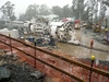
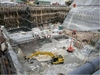
The Bogong power station works commenced in March 2007 with the construction of a 1:2000yr AEP flood protection bank between the site and the adjacent Lake Guy. A 4m deep layer of silt then had to be removed from across the site.
The design of the power station was such that it was to be founded on fresh rock, some 15m below the surface of the site and around 20m below the level the lake. A secant pile wall, surrounding the power station footprint was constructed to support the sides of the power station excavation and to minimise ground water ingress into the area. CFA piling techniques were adopted with the piles augured through colluvium and residual granodiorite down to fresh rock. The material within the secant pile wall was then excavated down to foundation level in five stages, with anchors and waler beams being progressively installed to tie the walls back.
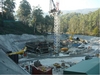
During excavation of the power station site, it was determined that there were significant benefits to the project in accelerating the construction of the power station, mainly to provide early access to the mechanical and electrical contractors responsible for assembling and commissioning the turbines.
Consequently, the 16 month construction timeline was reduced to 13 months and the 1.5m thick base slab of the station was commenced in October 2007. Overall dimensions of the Bogong power station are 45m long, 25m wide and 34m high. In all, 10,000m3 of concrete and 1700T of reinforcing steel were required in its construction.
The primary equipment used for the power station construction works consisted of:
• Favco STD1500 tower crane.
• RMD formwork systems.
• Putzmeister MX-28 placing boom and BSA-1409D pump.
The station was completed within the accelerated timeline and was handed over to the mechanical and electrical contractors to commence their turbine installation works in November 2008. These works are currently in progress with turbine #1 to be completed by late June 2009 and #2 by late August 2009.
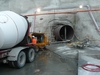
Running concurrently with the power station works, the high pressure headrace tunnel (HPHT) was also being constructed. The portal for this tunnel is located 15m to the southwest of the power station and immediately adjacent to the edge of the secant pile wall.
The HPHT is 1100m long and was excavated with an arched profile of nominal dimensions 4.2 x 4.2m. The inbye 400m was lined with unreinforced concrete with an internal diameter of 3.6m. The outbye 700m was lined with a 3m internal diameter steel liner, the annulus between the liner and the excavated rock filled with a 20MPa concrete.
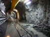
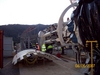
The portal and first 70m of excavation was through mainly extremely weathered Granodiorite. This was cut using a Mitsui S200 roadheader with steel sets and shotcrete being employed as ground support through this area. The transition to fresh granodiorite rock was relatively sudden and drill and blast excavation was commenced using rail-borne equipment. Temporary ground support consisted of resin encapsulated rockbolts and mine mesh.
The primary equipment used for the drill and blast works consisted of:
• Atlas Copco Raildrill 252.
• Hagglunds 8HR2 loader.
• 5 x Hagglunds 115-C muck cars.
• 15T Plymouth Locomotive.
• Charging deck / ANFO kettles.
Once excavation of the HPHT was completed, the permanent lining was installed. The concrete lining was undertaken using a 9m long, 3.6m dia steel form. Concrete was delivered into the tunnel using conventional agitator trucks and pumped through injection ports into the form. A minimum concrete strength of 2MPa was required prior to striking the form and through significant trialling prior to these works commencing, a mix was developed that would achieve this in eight hours. This relatively quick development of strength was essential in achieving the required 24 hour turnaround on the form.
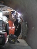
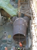
The steel lining for the HPHT consisted of 58, 12m long by 3m diameter steel modules ranging in thickness between 28–24mm and each weighing 25–32T. These were transported into the HPHT on rails using a purpose-built carrier supplied by Muhlhauser, Germany. Once in the tunnel, each module was positioned and welded internally on a single-vee preparation to the previous module using semi-automated FCAW equipment.
A production rate of four modules installed, welded and concreted in each week was necessary to maintain the programme. This was achieved through operating continuous shifts 24hrs/day, five days/week.
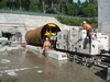
Welding times varied depending on the thickness of the pipe but typically, each joint took 20-24 hrs to complete with two welding machines operating concurrently. 100% NDT of all welds was required and the work was completed without the requirement for any repairs. Filling of the annulus between the steel liner and the excavated rock was undertaken once per week. A 20MPa self compacting concrete mix was developed which was capable of being pumped long distances.
Concrete was delivered to the portal and pumped up to 700m into the tunnel through a 125mm dia. high pressure delivery line using a Schwing BP-5000 pump. Typically 400m3 of concrete over a 10hr period was required for each cycle. The final connection of the waterway between the HPHT and the turbines is currently underway. This consists of a 45T bifurcation that splits the waterway into 2 x 2m dia manifold branches connected to the main inlet valves directly upstream of the turbines.
The bifurcation and manifold branches will then be encased in a 1000m3 reinforced concrete anchor block and backfilled with another 10m of fill material.
All material originally excavated from the power station site and the high pressure headrace tunnel have been stockpiled adjacent to Lake Guy. This material will then be recovered and used to bury the power station, once all construction works have been completed. The entire area will then be revegetated, effectively reducing the visual impact of the project on the surrounding Alpine National Park.
Downstream dropshaft
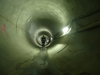
The downstream dropshaft basically connects the main headrace tunnel to the high pressure headrace tunnel. The excavated shaft diameter was 4500mm and after lining with concrete it formed an internal finished diameter of 4000mm. The required shaft depth was 96m. The method of excavating the shaft was by Raiseboring method using a Robbins LM97 Raiseborer with a 4.5m diameter reaming head.
However, before the raiseboring activity could begin the following had to be completed:
• Excavation of the high pressure tunnel.
• Excavation of main headrace tunnel beyond TBM Ch:812.50.
• Drill and blast a cuddy to accommodate the raiseboring unit.
Raiseboring activities commenced April 2008 and were completed in May 2008. The raiseboring activities continued 24/7 and average advancement rate of approximately 1.5m/shift. Spoil risings from the reaming of the shaft were collected from the base in the High Pressure Headrace tunnel and transported out to the spoil disposal bin by rail mounted spoil cars. The raisebore method resulted in a smooth line bore. Support of the shaft was provided by spot rockbolting and mining mesh as required.
The concrete lining of the shaft was constructed from the bottom up. A working platform was suspended above the shaft. A simple steel form panel shutter was used as the form. Concrete was poured in 4m lifts with one pour being completed each day.
The main headrace tunnel is a 5m dia, 5700m long tunnel, plus a 100m for the tunnel stub. The tunnel alignment traverses under the mountains of the National Park where tunnel depths exceed 200m and up to 400m. The majority of the vertical alignment of the tunnel is at 4% grade, this decreasing to 0.20% at the 600m radius approach to the downstream dropshaft.
The main headrace tunnel is on the critical path. Until the main headrace tunnel was completed the headpond drop shaft, constructed by raiseboring, could not commence. The main headrace tunnel was always envisaged to be excavated using a TBM.
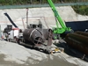
The GBR was used to determine the appropriate TBM. The GBR predicted competent rock of 145MPa average strength and a Q value of 10, which effectively suited a hard rock TBM over the distance of about 6500m. McConnell Dowell procured a 5m diameter, refurbished Robbins TBM.
The TBM was refurbished by Herrenknecht in Germany. The TBM had completed two previous projects in Europe, the last one being a water tunnel in Lugano, Switzerland. The TBM arrived on Site in June 2007.
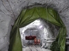
The TBM is a single gripper, main-beam hard rock machine, which basically involves the TBM gripping against the side walls of the excavated tunnel and propelling itself forward by way of four hydraulic propulsion cylinders connected to the main beam. The combined force of the propulsion cylinders is approximately 1000t. The rotating cutter head is connected to the main beam and series of six frequency controlled electric motors producing 1800kw. The TBM cutterhead is equipped with a total of 33 x 19” cutters. The maximum cutterhead thrust is 10,395kN and maximum head rotation is 10.9rpm. The gripping capacity of each gripper is 15,779kN, with a combined gripping lateral force of 31,558kN (approx 3000t). One stroke of the TBM is 1800mm and in anticipated conditions would take approximately 40 minutes.
The TBM is also equipped with a probe drill with a range of 360° and two roof bolting hydraulic rock drills for installation of rock bolts.
The TBM was named by local school children ‘Aurora Australis’. (Southern polar lights), representing the fact that the new tunnel and power station will bring light to homes.
TBM excavation began in earnest in August 2007. A launch tunnel of 134m was constructed in advance to accommodate the assembly of the TBM and the back up which was 140m long. The GBR predicted intact rock strengths for SW-Fr granodiorite would have a mean UCS of 145MPa with an upper bound of 235MPa. Indeed the GBR further stated that for 70% of the granodiorite will lie between 110MPa and 180MPa.
Based on the above anticipated rock condition advance rates were expected to achieve 535m per month. However actual observed rock strengths in the main headrace tunnel during tunnelling were on average 180MPa, some 24% higher than anticipated. This has resulted in an average advance of approximately 340m per month.
McConnell Dowell elected to provide a continuous conveyor system to covey excavated rock material from the TBM to the stockpile area. The continuous conveyor system was procured from H&E Logistik GMBH of Germany.
The conveyor system, as the name suggests, is a continuously extended belt conveyor originally developed for use in the mining industry. The belt itself is 650mm wide and is able to transport 275t/hr. The conveyor is connected in the tunnel crown by chains. The forward end of the conveyor (tail end) is fixed to and towed by the TBM back up. The belt structure and troughing rollers are inserted at intervals of about 3m.
As the tunnel advances the conveyor is extended with 600m of belt sections. Each new section is jointed by the vulcanising process. The conveyor belt is equipped with two 90kW drive units. The belt speed of the conveyor is 2.8m/sec. The spoil is transferred to the stock pile by a transfer conveyor which crosses above the Bogong High Plains Road. The excavated rock is re-used by local authorities for road rehabilitation projects.
Key dates
At the time of writing this paper the power station and downstream dropshaft were substantially complete. The main headrace tunnel was successfully completed on 23 April 2009. The TBM has been dismantled and the remaining components left in the tunnel stub. The headpond dropshaft is currently being raisebored.
The power station, high pressure headrace tunnel and downstream dropshaft will be ready to receive water by the end of June 2009. The main headrace tunnel and headpond dropshaft will be ready to receive water by the end of August 2009.
The turbines were being installed in the power station with preparation works ongoing for wet commissioning, which is expected in mid September 2009. The turbines are expected to be operational by October/November 2009.
Paul Thomas is the project manager for the Bogong power development project. Email: Paul.Thomas@macdow.com.au
Thanks are given to Shaun Paul, Section Manager Power Station & High Pressure Headrace Tunnel, for contributing to the article
| Construction work |
| A wide array of construction techniques, plant, and equipment were used and continue to be used in the construction phase. These include: |
| Key design requirements |
| • Comply with required design life of 100 years. |