Group dynamics
21 November 2005An interdisciplinary research group has been created at the Lulea University of Technology to help develop new methods in design, operation and maintenance of hydro power equipment
Sweden’s abundance of natural resources allowed hydro power to play a key role in the development of the country. The expansion of this power source in the first half of the 20th century gave Swedish industry a leading position in the field of power generation, with innovations such as high-voltage power transmission and new technologies being introduced. However, a slowdown in the construction of new power plants lead to an over capacity at the end of the 1960s, bringing with it large changes in industry and academia. Education and research into this power source had reached a limit, which could have had an effect on the nation’s welfare and growth. As a result, structural changes at the end of the last century saw the beginning of a large refurbishment period of the Swedish hydroelectric industry.
Porjus hydro power centre
To aid in this refurbishment project, Porjus Hydro power centre was established in 1994 to run education, research and development programmes in the field of hydro power. The result of a SEK100M (US$13M) investment from Vattenfall AB, Kvarner AB, and ABB, the working department and the county administrative board from Norrbotten, it features two world full-scale 10MW turbines, exclusively dedicated to education, research and development.
The first machine, U8, was inaugurated in 1997, followed a year later by U9. U8 is equipped conventionally and has, to date, been used in for educational purposes, while U9 includes more recent developments within turbine, generator and bearings technologies and is mostly dedicated to R&D. Both turbines are coupled to the grid. They can be started and stopped at any time as well as run manually, allowing the design of specific experiments, such as start and stop. Both turbines are located beside each other and share the same surge tank and downstream tunnel, and have a head of about 55m with a maximum flow rate of approximately 20m3/sec.
U8 is equipped with a Francis turbine composed of 15 runner blades, 20 guide vanes and 19 stay vanes. The runner has a nominal diameter of 1420mm and a maximum diameter of 1750mm, while the generator is of conventional type, with a modern control system. Two systems allow different types of measurements such as pressure losses, vibration, bearing, cooling water, and head. The machine represents a unique opportunity to develop skills by testing different scenarios which occur in the lifetime of generating equipment.
U9 is equipped with a Kaplan turbine composed of six runner blades, 20 guide vanes and 18 stay vanes. The runner has a diameter of 1550mm, positioned 7m below the tail water and rotates with a frequency of 10Hz. The generator is a Powerformer high voltage generator, which generates and exports electricity directly to the grid without the need of medium voltage switchgear and step-up transformer, allowing a higher efficiency and reducing maintenance and environmental impact. Several parameters such as flow rate, load, frequency, blade angle, rotational speed, headwater, tail-water and electrical parameters are constantly measured. Average values over one minute are automatically sampled and saved. The power rate is measured with an ultra sonic flowmeter installed on the penstock, which employs ultrasound to measure average fluid velocity along several paths, and then calculates the mean flow rate. The instrument measures the flow rate within 0.5% according to the manufacturer.
Several experiments have been performed on U9 since its inauguration, on: turbines [11, 27], bearings [63, 64, 23, 60] and generators [36, 42, 41, 40].
The group
A research group composed of Ass. Prof Jan-Olof Aidanpää (rotor-dynamic), Ass. Prof Michel Cervantes (turbines), Ass. Prof Sergei Glavatskih (bearings) and Prof. Thommy Karlsoon (generator) has been created. Generator technology is not a research area at Luleå University of Technology, therefore close collaboration with Uppsala University began some years ago with the help of Prof. Thommy Karlsoon, a joint professor to Luleå University of Technology who works as a generator specialist for consulting company SwedPower.
The research group aims to develop world leading competencies and knowledge for cutting-edge technologies in hydro power generation. In order to realise this dream, it have the following agenda:
• Strengthen and develop the interdisciplinary research group.
• Establish a model laboratory to study specific parts of the rotor system.
• Establish a full-scale research facility for interdisciplinary research.
The following article offers a description of the power system from a dynamic point of view to obtain an overall picture, and is completed with a detailed description of the bearings and turbines. The state-of-the-art in each field is presented, together with suggestions for further development. Also included are details on experiments planned for 2006-2008.
System descriptions
Rotor-dynamics
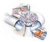
Rotating machinery consists of discs, shafts, bearings and support structures (Figure 1) . In addition, various machine elements can be added to the rotating machinery, e.g. gears, clutch and brakes. The term rotor is often used to denote the rotating parts, while stator or stationary denotes static parts of the machine. The term ‘rotor dynamics’ is used when the dynamics, i.e. time dependent forces and vibrations, of rotating machinery is studied or analysed. ‘Dynamics’ focuses on the natural frequencies of the system. In rotating machinery these natural frequencies are due to gyroscopic effect, which is a function of the driving frequency of the rotor. These natural frequencies give rise to high vibrations and thus have to be determined at the design stage to avoid dramatic consequences during operation. Several catastrophic events have been reported on rotating machinery [see 29, 46, 12].
The main reason for rotor dynamic analysis is therefore to find the natural frequencies as functions of the rotating speed, as in the Campbell diagram. The complexity of industrial rotating machines induces several approximations in the mathematical modelling, the degree of complexity of which depends on the actual problem. However, the presence of non-linear phenomena [61] makes such model rapidly complex.
Historically, rotor dynamics have been developed for high speed rotors such as gas and steam turbines. In hydro power applications the same tools and models have been used with small adaptations to the specific constraints – a rotor dynamic model needs to include electromagnetic forces from the generator, bearing models and models for the turbines interaction with the fluid.
The influence of magnetic forces is significantly higher than in other applications, since the relative air gap is much smaller than in turbo generators. The deformations due to thermal expansion cause shape distortions and eccentricities that need to be considered. In turbo machinery the rotor is normally mounted horizontally, which, due to gravity, results in well defined static loads and therefore allowing a working position to be evaluated in the bearings. This working point gives a linearised stiffness and damping which is used in the rotor dynamic model. In hydro power applications, the rotor is normally vertical and therefore the working position or the load is not well defined. The turbine’s interaction with the fluid will also affect the system by damping, stiffness and inertia effects. Today, there are some rules of thumb but there is a need for scientific evaluation to improve the models. The goal of rotor dynamic research is therefore to increase the predictability of the dynamics, reducing vibrations and increasing the reliability.
Rotor dynamic research in hydro power applications focuses therefore on the development of models and measuring techniques in order to create better tools for simulation and analysis. By increasing the predictability of the dynamics, tools can be developed to reduce vibrations and increase reliability. The influence of new components can be analysed before revisions are made, so early design changes can be suggested. Furthermore, stresses and loads analysis during different operating conditions can be performed to identify critical components and develop tools for life time evaluation.
Bearings
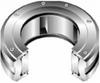
Fluid bearings in hydro power stations encompass thrust and journal bearings. Journal bearings are employed to position the shaft in the radial direction, they are usually only lightly loaded and the main problem encountered in practical applications is their dynamic performance, which reliable models are required to describe. The models rely heavily on a number of empirical parameters that must be determined in the tests. Thrust bearing supports the weight of the shaft plus the hydraulic thrust of the water acting on the turbine runner, these types of bearings are heavily loaded and can carry significant loads of up to 6000t in some power plants.
Dynamic aspects of thrust bearing operation are of less importance compared to journal bearings. The main problem is bearing reliable operation in transient and steady state modes. There is an industrial demand for more efficient thrust bearings, capable of operating reliably at higher duties and in conditions with regular stops and start-ups, a factor brought about by the deregulation of the Nordic energy market. The situation is aggravated by a forthcoming modernisation of old power stations in the Nordic countries – new bearings and environmentally adapted oils are in great demand.
Turbine
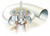
There are two types of turbines: reaction and impulse. Reaction turbines have the runner surrounded by water with the upstream region under high pressure and the downstream under low pressure, impulse turbines, on the other hand, have the runner under atmospheric pressure. Kaplan and Francis turbines are in use at most Swedish hydro plants and are therefore the focus here. Kaplan turbines are of axial type, while Francis turbines are of radial-axial type, (Figures 4 and 5).
While the flow at the inlet of the penstock and the outlet of the draft tube are relatively simple, complex flow phenomena such as turbulence, unsteadiness, separation and swirl appear in between, a challenge for any fluid mechanics. Turbulence is characterised by randomness and a wide spectrum, whose lowest frequency is proportional to the ratio of the mean velocity to the hydraulic diameter of the water passage.
Two main types of spiral exist: concrete and metal [50]. The spirals in concrete generally have a polygonal cross-section with a ‘T’ or ‘b’ shape and are used for low head. The spirals in metal have a circular shape and are used for middle and large heads; the roll of the spiral is to deliver an axis-symmetric flow to the runner. However, the presence of guide vanes to regulate the flow rate and stay vanes to strength the structure causes wakes, which influence the transfer of energy from the flow to the shaft. The rotation of the runner induces pulsations upstream and downstream frequencies that are coupled to the runner frequency and number of blades. The relative position of the runner to the tailwater may give rise to cavitation, which induces high frequency fluctuations. Furthermore, the geometrical form of the runner and the draft tube induces specific pulsation at part load, which also influences the transfer of energy.
Rotor-dynamic
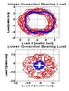
Large radial forces have affected the guide bearings in the generators of a number of hydro power stations. These forces can cause damage and/or failure of the bearings, resulting in an economical loss [1]. In electrical machines almost 40% of these failures can be related to bearing failures [48, 7]. One reason for the radial bearing load is static or dynamic misalignment between rotor and stator – this misalignment results in a non-uniform air gap and consequently a non-uniform magnetic field [59, 57, 58]. Measurements of air-gap eccentricity in electrical machines are often based on measurements of the change in the air-gap field with loops or coils [9, 38].
Knowledge of the radial magnetic pull force acting on the eccentric rotor is important for the mechanical design and maintenance of a hydro power generator. A number of equations are available to calculate the magnetic rotor pull for an eccentricity up to 10% of the average air-gap [5, 52, 26]. Models have been improved to a certain extent by taking into account the effect of saturation [15, 53, 8, 47].
When measurements of bearing load are performed in generators, the load sensors are usually built in behind the bearing pads with similar technology as described in [25]. Measurements with strain gauges attached to the bracket base plates have been shown in [47]. But, on a great number of generators, the base plates are pre-loaded and therefore not suitable for measurements. However, the majority of hydro power generators are not equipped with facilities for load measurement and the reconstruction, which is necessary to provide the bearings with load sensors, is associated with heavy expenditure. In [30] an alternative method was presented for measuring the radial bearing force. This method is based on strain measurements at the bearing supports and the force is calculated using beam theory. This method can be used without modification of the bearing house or other mechanical parts. The measurements indicate clearly that electromechanical and fluid forces strongly affects the dynamics of the rotor. The electromechanical effects on the stability were then studied in [31, 32]. They show that nonlinear electromechanical load models are sometimes necessary in order to design a reliable machine.
The method in [30] was further developed to measure the bearing stiffness and damping [33]. The paper clearly shows that stationary points seldom exist in hydro power applications. Therefore new bearing models for hydro applications need to be developed.
In the field of fluid dynamics, the frequency content of the forces acting on the turbine is of interest. An overview of the vibration problems within a Francis turbine is given in [28]. The influence of draft tube surges are discussed in [51]. Simulations of turbines and impellers with interactions to stationary parts have been carried out in [54, 55, 39, 65] as well as measurements in [16, 4, 62].
In a recent paper [37], a rotor dynamic model including the fluid and electro mechanical forces is investigated. The paper’s key issue was to investigate how accuratly a simplified model can predict the behaviour of the system. It was concluded that the unbalance together with the geometric properties of the turbine and generator is certainly the source of the dominant frequency peaks in the measurements. The results also indicate that a multi physical coupling of the components in the rotor system is needed to predict the behaviour of the whole system.
The degree of complexity of rotor models of today is unsatisfactory to predict the dynamics of hydro power rotors, with undesired vibrations and failures likely to occur. The goal of rotor dynamics research is to increase the reliability by improved simulation models.
Today, bearings are modelled by a linear isotropic stiffness, which is a strong simplification. It is likely that even the simplest model needs to be orthotropic and due to different fluid and magnetic forces, the bearing properties are likely to be time dependent. The rotor dynamic group has undertaken some initial measurements in an attempt to analyse this. However, new investigations are necessary in order to model more accurately bearings.
The fluid forces are today implemented by simple rules of thumb. Measurements so far indicate the necessity to implement the fluid forces in the rotor model to predict the vibration levels. Different types of turbine need to be analysed in order to develop simplified load models. The fluid will, in addition to forces, add system properties such as mass, stiffness and damping to the model. All these features are specific to hydro power rotors and from a rotor dynamic point of view these rotor models are underdeveloped. After all these aspects have been analysed, a realistic simulation of vibration amplitudes and eigen-frequencies could be performed. By analysis of bearing forces due to start-ups and load cases, it is possible that realistic models for maintenance and increased reliability can be obtained.
One important step to develop better models is that good measurements can be performed on real machines. It is also necessary that this machine can be modified to experimentally evaluate different models – therefore, the access to Porjus U9 is crucial.
Bearings
Three main parameters must generally be measured to quantify bearing steady state performance. These parameters are power loss, bearing operating temperature and oil thickness.
Power loss is usually estimated by a calorimetric technique. It is applied to the oil flow supplied to the bearing. Ignoring the heat transferred from the oil into the shaft and housing the bearing power loss is the product of a temperature rise from supply to discharge, oil specific heat and oil flow rate. For large bearings this technique is applied to the cooling water flow running through a heat exchanger. Bearing friction torque can also be measured by strain gauges mounted on the shaft but sensitivity may suffer [20].
Unlike other parameters, bearing temperatures can be measured relatively easily. Temperature monitoring of the bearing pads is now a well-established method to detect overheating and to avert bearing damage. Measurement of oil temperature, however, is more difficult [21].
Oil thickness is the most difficult quantity to measure in practice. This is probably due to the lack of adequate sensors capable of sustaining high pressures and temperatures, plus provide sufficient accuracy combined with high sensitivity and stability in the micrometer range; oil in the bearings is usually from 20 to 100 µm. Sensors based on inductive and eddy current techniques are the most frequently used due to their independence of oil properties. The sensors can be attached to the pad, installed in the pad or mounted in the collar. One of the problems encountered with this type of sensor is temperature compensation. The sensor output signal drifts with temperature, therefore compensation for scale factor and offset shifts is required. The thermal problem is also inherent in capacitance sensors. Another approach is based on optical methods. The main drawback with optical and capacitance techniques is their dependence on oil properties that are a function of temperature and pressure [24].
Dynamic measurements in journal bearings are required to obtain bearing damping and stiffness. Accurate measurements of journal bearing dynamic characteristics are difficult, since the displacements being measured are very small (µm), the forces can be very large (kN) and the oil temperature has a significant impact on the results. Consequently, despite the best efforts of many researchers, there is still a real need for experimentally measured bearing dynamic characteristics [49]. A review of trust bearing design can be found in [19].
Turbine
Experimental investigations of flows in turbines focus essentially on flow rate, pressure and velocity measurements. Instruments and methods for the measurements of these parameters in a controlled environment, i.e. a laboratory, are well developed. The development is the result of nearly a century of work with model testing within the hydro power industry and the academia. A leading university in such measurements is Ecole Polytechnique Fédérale de Lausanne, Switzerland, which has performed numerous measurements on a Francis model, see [13].
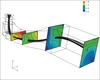
Model tests are essential in the construction and refurbishment of hydro power stations. A laboratory for model testing is available in Sweden at Vattenfall Utveckveling, Alvkarleby, Sweden. However, simulation tools are taking a larger place; an example is the MATH project at Hydro Québec [34]. More detailed information of the flow is obtained with simulations, see figure 8. The lack of dynamic similarity between model and prototype, i.e. the full-scale machine, necessitates scale-up formula to estimate the prototype efficiency from the model efficiency. The scale-up of the model efficiency is an old problem, which is still under development, see Anton [3] for a summary and the latest development. Models are driven with an electrical motor, introducing new boundary conditions compared to the prototype. Measurements on a full-scale machine such as Porjus U9 offer world unique possibilities to study the influence of the flow on the rotor. Measurements, especially pressure and strain, have already been performed on large machines, see e.g. [45]. The challenge resides in the application of well develop laboratory measurement methods to the experimental conditions inherent to an industrial environment.
Flow measurements are an essential parameter in hydro power to estimate the efficiency and the different dimensionless parameters necessary to perform experiments on the geometrical similar model. Efficiency measurements are currently of great interest with the implementation of the green certificate scheme in Sweden, which makes turbine refurbishment affordable. Several methods exist; the most popular absolute methods are the propeller method, thermodynamic method, Gibson method and acoustic method. The thermodynamic method is well developed for high head machines of Pelton type. The Acoustic method is the most accurate for low head turbines, which compose most of the Swedish industry. However, this method is expansive and difficult to implement. The Gibson method is arguably the most attractive. A standard from the International Electrotechnical Commission exists; the IEC41. The standard is applicable for certain conditions, where the mean velocity times the length of the measuring section has to be higher than 50. Luleå University of Technology is working on the development of a method for very low head turbines where conditions specified in the standard are not satisfied, see Lövgren[43].
Pressure measurements are the least complicated measurements to implement and perform in such machines, especially wall pressure measurements. Pressure measurements in the flow with the help of Pitot tube are less accurate due to its sensibility to the flow angle. However, velocity information is also gained during the measurements. Such measurements have already been used at Porjus U9 [11]. Sensors of different sizes, from 1mm in diameter upwards are commercially available. Of interest is the implementation of pressure sensors on the pressure and suction sides of the runner blades to estimate the amplitude and frequency of the forces acting on the runner, see e.g. [17, 44, 18] for measurements on a Francis model. Such experiments necessitate wireless technology for signal transmission to the data acquisition system. The technology is commercially available. To these pressure measurements, blade strain fluctuations could be done to investigate fatigue failure.
Pressure measurements are highly interesting. However, velocity measurements are of the same interest, since mechanical energy is the sum of kinetic energy and pressure. Experimental pressure and velocity measurement are essential to understand flow phenomena and therefore develop scaled-up formula. Furthermore, such measurements allow the validation of turbulence models and optimise hydraulic machines. The methods of interest for velocity measurements in water turbines are Pitot tube, laser Doppler anemometry (LDA) and particle image velocimetry (PIV), see [35]. All methods are familiar to the division of fluid mechanics. The second has been extensively used on the turbine model at Älvkarleby, (see www.turbine-99.org for more details), while the second method has been developed recently at Luleå University of Technology. The methods have different advantages and drawbacks. The two last methods are optical and therefore do not disturb the medium as the first one; furthermore, they are very accurate but more time-consuming. Particles are needed in the liquid for these methods to operate. This is an issue in full-scale machines, since seeding cannot be done as in a laboratory. Preliminary water analysis indicates that the amount of particles present in the water of the Luleå river allows such measurements. Another issue is the optical accessibility necessary to perform such measurements, which oblige the installation of windows with custom geometry.
Areas for further development
Rotor-dynamic
As mentioned earlier, rotor dynamics tools and models have mainly been developed for high speed rotors such as gas and steam turbines. In hydro power applications a rotor dynamic model needs to include electromagnetic forces from the generator, new bearing models and models for the turbines interaction with the fluid. In the development of new theories it is essential to verify models against reliable measurements. Fundamental for a rotor model is that torsional and lateral natural frequencies can be measured at different driving frequencies and loadings.
In hydro power applications the flow in the turbine, dynamics in the bearings and the electromagnetic load will all affect the eigen-frequencies of the rotor. Therefore the measurements and predictability is a key problem to be solved in order to develop good rotor models. Identification of the power transmission through the system will result in better load models. By measuring pressure on turbine blades, torque in the rotor, bearing loads and the power output, models can be developed looking at how different loads are transferred in the system. From these load models it will be possible to perform simulations with higher accuracy on vibration amplitudes and bearing loads. In the case of torsional vibrations it will be possible to create electromechanical models to simulate the dynamic and electric interaction. One important load on hydro power rotors is the magnetic force due to eccentricity. Displacement and temperature measurements on the generator stator and rotor would be useful in the analysis of static and dynamic eccentricity. To develop better bearing models it is essential to understand the rotor displacement and bearing forces. Then the rotor orbit, bearing stiffness and damping could be measured and used for verifying new bearing models. If all bearing forces can be measured together with the generator eccentricity, the force and phase in the turbine could be solved by Newtons equations. Together with measurements of the pressure distribution on the turbine blades, a detailed load model may be obtained.
The first target of the measurements has to be the development of more realistic rotor models. With such models, more reliable machines can be developed by optimisation of driving conditions. In retrofit applications new design modifications can be evaluated in order to increase reliability and to avoid failures. Another target is to develop methods for the maintenance of the machines, which may combine simulation together with measurements. Such instrument may allow the evaluation of the maintenance intervals. The research question is then to find which measurements and simulations that are needed in order to predict the life span of components.
Bearings
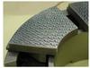
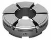
The most reliable and best overall performing type of fluid oil bearing is the tilting pad bearing. Each pad rests on a pivot and is free to incline to any angle that will give the optimum wedge for any combination of speed-load-oil viscosity.
The main limitation in existing bearings is surface material, commonly tin or lead based babbitt. It is used to prevent shaft damage and to trap contaminative particles. This material starts to weaken at elevated temperatures leading to possible bearing failure. During start ups and stops babbitt comes into contact with a shaft and the risk of bearing seizure is high. To prevent this contact, an oil jacking system is used. Oil is pumped at high pressure into the gap between the shaft and the bearing and the dangerous contact is eliminated. Unfortunately, this jacking system is expensive, energy consuming and not sufficiently reliable. In addition, conventional babbitted bearings are subject to severe thermal deformations that significantly limit bearing operation.
An alternative material that has been attracting the attention of bearing designers and end users over the years is PTFE. It is already widely used in dry sliding bearings and it may also play an important role in hydrodynamic bearings due to its outstanding properties: the broad temperature range, excellent anti-seizure properties, and the superior resistance to chemical attack and moisture. This material also has also the lowest coefficient of friction of all solid materials. Low wear resistance and the negative effect of temperature on its compressive strength can be improved by formulating various compounds.
The existing bearing theory and computer models do not take into account bearing surface material since the effect of babbitt on bearing operating parameters such as temperature, pressure, and oil thickness has been considered to be negligible. The situation is different with PTFE which is an excellent thermal insulator. Moreover, PTFE considered resilient, which is considered an important feature as contact stresses are reduced and a more favourable pressure distribution over the bearing pad is obtained. Maximum pressure is therefore reduced and the bearing pad can be made smaller. Smaller bearings operate with lower power loss.
The resilient nature of the PTFE also implies that the bearing work surface must initially be machined in a certain way to avoid a divergent gap that cannot carry load. All this requires availability of an appropriate computer program that can predict PTFE bearing the operating parameters and help in designing the profile of the working surface. Although the laws of thermodynamics are well understood, there is no complementary simple thermodynamic model of bearing performance for the prediction of operating parameters. In addition, even today’s computer models rely heavily on test data for setting up a number of thermodynamic parameters used in the performance calculations. A verification of the computer bearing model must therefore be carried out through a comparison with the experimental data. PTFE-faced bearings can be tested in Porjus. Based on the verification, all the required empirical thermodynamic parameters will be identified.
Environmental issues are also of importance. A significant amount of oil used for bearing lubrication creates a potential hazard to the environment and worker safety. Oil may leak and come into contact with a sensitive river ecosystem causing adverse effects. New environmentally adapted lubricants should be tested in full scale.
Boundary lubricated bearings in the runner can also be improved. The main question is how environmentally adapted water turbines with enhanced performance and reliability can be produced and run at lower cost. By combining experimental and theoretical research studies quantification of friction and wear of alternative self-lubricated (at dry and moisturised conditions) and water lubricated materials in conformal contacts will be made. Today, it is not clear how operating environment affects performance of polymeric materials. What are the dominating wear mechanisms? How can the wear processes be simulated and how can an optimal bearing material be selected? There is a demand for knowledge of how to choose material and design environmentally adapted water turbine bearing/bushing with increased service life, enhanced performance and reliability as well as for methodology of transferring test data from standardised model tests into full-scale application.
Turbine
CFD is today unable to estimate the efficiency of a model with the same accuracy as laboratory tests, where efficiency is measured with ±0.2%. However, the unsatisfactory comprehension of scale-up effects makes the use of CFD to optimise hydro power plant efficiency an important tool. Furthermore, CFD may allow automatic optimisation of the entire system. Therefore, CFD is expected to be the future of flow related problems within hydro power and focus should be on its development. Much work is still necessary.
CFD today allows the simulation of different parts of a hydro power plant such as draft tube and rotor-stator. The actual computer capacity provides poor accuracy, since large grids and simple turbulence models such as the standard k - epsilon are generally used. The complexity of the flow in a hydro power plant needs more advanced turbulence models and wall function to simulate accurately the features of such flow, especially in the draft tube. The development of such turbulence models is possible if high quality experiments are available for validation. Experimental data is today limited to specific test cases; GAMM and Turbine-99. More data should be available to the computational community. Furthermore the development of workshops such as the Turbine-99 workshop dedicated to draft tube flow simulation should be encouraged.
Efficiency measurements on prototypes have a poor accuracy compared to model efficiency measurements due to the difficulty to measure flow rate. As previously mentioned, the Gibson method represents an attractive method for low head, typical in Sweden. The method needs further developments to give accurate results when the conditions specified by the standard are not satisfied.
Prototype efficiency is obtained from model efficiency, since model and prototype are not running in dynamically similar conditions. Model efficiency is lower than prototype efficiency, since viscous effects are relatively more important. Scale-up formulas are used to extrapolate the prototype efficiency from the model efficiency. Detailed measurements on model and prototype will be of great help in the development of such formula.
Planned experiments at Porjus
The principal objective of the experiments at Porjus during 2006-2008 is to get detailed and reliable experimental data to develop more realistic rotor models. Therefore, extensive experiments on the different parts of the machine are necessary simultaneously. During the experiments, the following parameters will be measured:
• Torsion of the shaft with strain gauges.
• Generator voltage, current and magnetic field.
•Stator deformation and air gap with the help of magnetic field measurements and strain gauges.
• Bearings displacements and forces with strain gauges.
• Oil film temperature, thickness, pressure and losses.
• Forces on the runner blades-cone-shaft with miniature pressure sensors.
•Vibrations of the rotating and stationary parts with accelerometers.
•Standard parameters such as flow rate, rotational speed, tail water, head water, with more.
Velocity and pressure measurements at different sections in the machines will also be performed with laser Doppler anemometry and Pitot tube. The measurements will focus on the determination of specific boundary conditions and validation sections to support simulation. Unfortunately, such measurements are impossible to perform simultaneously with the other measurements.
Senior researchers will primarily be involved in the project to guarantee the scientific relevance and schedule. The first year will be dedicated to a detailed planning of the different experiments such as transients as well as the purchase, installation and test of the different instruments. The second year will focus on the measurements and the third on the analysis of the results as well as complementary measurements. The instrumentation is expected to be permanent on the machines to allow a continuous development in the area of power generation. After the first phase, more detailed measurements will be designed in each to allow models development.
The project has been initiated by Luleå University of Technology through Hydro Power University in collaboration with the municipality of Jokkmokk and the owners of the Porjus Hydro power Centre foundation – Vattenfall, GE Hydro and Alstom. The project is also open to other companies under certain conditions, which have to be individually discussed. Please do not hesitate to contact Dr. Michel Cervantes for further information.