Building Jinanqiao Dam
29 November 2010Yong-Wen Hong and Cheng-Bin Du present details on the design and construction of the Jinanqiao RCC gravity dam, a 160m high structure located in China’s Yunnan Province, in a region of high seismicity
Located on the middle reaches of the Jinsha River, Jinanqiao hydropower plant is the fifth in a series of eight hydroelectric power stations. The dam site is located 50km away from Lijiang City in Yunnan Province in China, and has a catchment area of approximately 237,400km2. The average inflow at the dam is 1640m3/sec, annual runoff is about 51.7km3, normal reservoir water level is 1418m, with a corresponding storage capacity of 847Mm3, including 313Mm3 of regulated capacity. The powerhouse is located downstream of the dam, with an installed capacity of 2400MW (4 × 600MW).
The project comprises a dam, power plant, crest spillway, and stilling basin on the right bank, two bottom outlets for sand sluicing and flood discharge on the right of the dam, and the third bottom outlet for sand sluicing on the left of the dam.
The dam is a roller compacted concrete gravity dam with a crest elevation of 1424.00m; the maximum dam height is 160m with a crest length of 640m and downstream slope of 1:0.75. The upstream slope below elevation 1335.00m is 1:0.3, and the concrete volume of the dam is 3.92 × 10⁶m3. Five openings at the crest with a size of 13m × 20m form the spillway; its discharge capacity is 14980m3/sec (5000 years design flood). There are four penstocks, one for each hydroelectric unit. The diameter of each penstock is 10.5m, flow is 605m3/sec, and the rated head is 111m. There are four access sluices whose dimensions are 9m × 14m, as well as four emergency gates with dimensions of 9m × 12m in the power station intake. The dimensions of the powerhouse are 213m × 34m × 79.2m (length × width × height); four sets of 600MW Francis turbine units with runner diameters of 8m are installed within the power plant.
According to research results from the Institute of Geology, State Seismological Bureau of China, the basic seismic intensity of the dam site is 8 degrees on the Chinese intensity scale. The peak horizontal ground acceleration of the bedrock site for earthquake with return periods of 5000 and 10,000 years is 0.4 g and 0.475 g, respectively.
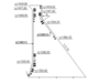
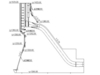
This project was approved in August 2003; and the river was closed at the end of December 2005 (Figure 1). The main construction works began in January 2006, with the dam foundation excavation completed and the first concrete poured in February 2007 (Figure 2). The project’s first generator went into operation in June 2010.
Design and construction measures
Integration of dam body and powerhouse to improve sliding stability
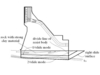
There is still a lack of information on the special seismic design features of large RCC gravity dams in areas of high seismicity. Under seismic action high dynamic tensile stresses occur in the dam body, especially at locations of geometrical changes. In addition, the sliding stability of the dam has to be guaranteed. In Figure 4 two sliding failure modes for the dam foundation are shown, which account for the special geotechnical features in the dam foundation. Two structural systems are shown where (a) the powerhouse and the dam body are separated, and (b) where the dam and the powerhouse are acting as a monolithic structure by grouting the joint between the dam and the powerhouse.
In system (b) the sliding stability can be improved considerably (Yuan, 2008).
The incomplete cut-off of the transverse joints
Because of the special features of the foundation rock, the sliding stability of the left bank concrete blocks under seismic action is of major concern.
In order to improve the sliding stability of the dam, and to mobilize the whole mass of the dam, the depth of the contraction joint is only 2/3 of the dam thickness in each RCC layer (each RCC layer is 30cm deep). The electronic power cutting machine, with cutting blade width of 1cm, is used to generate the joint at the presetting transverse joints after each layer is compacted by the roller. The depth of the cut-off is 20cm, which approaches two-thirds of the thickness of the layer. The 10cm thick RCC, without cutting in the layer, still interconnects. Non-woven fabrics are embedded in the joints, and then a round stick machine is used to roll twice on the joint. The contraction joints are filled with non-woven fabrics, causing the construction joints to be weakly connected induced joints that are not only good for temperature stress releases but also enhance the integrity of the dam.
The nonlinear time domain seismic analysis of a dam with 10 transverse joints shows that by this measure the integrity of the dam can be increased significantly. Compared with the completely cut-off contraction joints, the maximum displacement of the dam along the river direction was reduced from 8.49cm to 7.64cm, and the maximum displacement of the dam across the river direction was reduced from 5.02cm to 2.09cm. The loads considered in the calculation include self-weight, hydrostatic pressure, sediment pressure, uplift pressure, wave pressure, and the design earthquake effect. Figure 5 shows the construction process of the contraction joints. By this special joint, the temperature cracks can be avoided, and the speed of construction can also be increased.
Earthquake-resistant steel bars design
The parts of the dam where the shape changes during strong ground shaking are the weak regions. The maximum dynamic tensile stress is generally 2 MPa and may reach 3 MPa in some areas; particularly on the surface and the corner edges of the dam. According to the 180-day strength of the C9020 concrete, the dynamic tensile strength that approaches 3.15MPa meets the requirements in most parts of the dam (Hong, 2006).
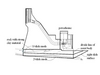
In addition, in zones of high dynamic tensile stresses steel reinforcement is provided. Two layers of steel bars with a diameter of 28mm (steel bars with a diameter of 36mm are embedded at the bracket support) are provided with a spacing of 20cm. The layout of the reinforcement is shown in Figure 6.
The stilling basin arrangement
The main bedrocks at the dam site are basalt and amygdaloidal basalt, although single rock has high strength, developed joints and fractures which can cause low integrity. The bedrock in the riverbed has joints filled with chlorite, therefore the scour resistance of the rock is low. In addition, there are some loose accumulation bodies, B2 and B20, distributed over the downstream side of the dam on the left bank. B2 is in the plant bedrock mass and the excavation slope at the end of the stilling basin. B20 is in the zone from which energy is dissipated to release, and its edge extends to the river.
Operation of the spillway on the right bank will cause scouring in the impact area of the water jets and a mound would be created, which can affect the safe operation of a hydropower station.
Setting up a high lip at the end of the crest spillway
The maximum head for the Jinanqiao hydropower station is 111m. The maximum flow velocity at the bottom in the stilling basin is 40m/sec. According to the hydraulic model tests, the ski-jump with a height of 6m causes energy dissipation by air entrainment, and the velocity of the flow at the bottom is reduced to 16m/sec in the stilling basin.
Strengthening measures of the dam foundation
There are some factors that negatively affect the sliding resistance in the dam foundation. For example, the deformation modulus and the strength of the jointed rock mass are low for the plant-dam foundation. Because there is a faulted bed plane on the epidote quartz that is distributed over the left bank of the dam foundation, the deep and shallow-layer sliding stability needs to be studied. In the nonlinear finite element analysis, stability safe factors for deep-layer sliding are 1.12 and 1.18 for usual static loads and seismic loads, respectively. The stability of the dam foundation satisfies the Chinese Code requirements. The horizontal displacement at the dam crest is less than 5cm for usual load combinations including self-weight, hydrostatic pressure, sediment pressure, uplift pressure and wave pressure and is less than 8.5cm in the seismic load combinations.
The physical and mechanical properties of the fractured jointed rock mass are reduced because of the unloading and reloading effects in the excavation process. In order to increase the deformation modulus and strength of the fractured/jointed rock mass, the high-pressure consolidation grouting method is used. The maximum grouting pressure is 2 MPa, and ordinary cement and ground fine cement are chosen for grouting.
Treatment of the accumulation body on the left bank
There are three collapse accumulations distributed around the dam. The collapse accumulation body B1 on the left bank is distributed upstream of the dam. It is about 490m away from the dam, and its volume is about 246×104m3. The distribution elevation of the front edge is 1400m. The second collapse accumulation body B2 is distributed downstream of the dam. It is about 250m away from the dam, and its volume is about 84×104m3. The distribution elevation is about 1370-1495m. The third collapse accumulation body B20 is also distributed downstream of the dam. It is about 450m-650m away from the dam and its volume is about 226×104m3; in addition, its maximum depth is 65m, and the lowest part of the leading edge extends to the river.
According to the analysis of the anti-slide stability, the main treatment measure of B1 is monitoring and protecting the slope. The measurements of B2 and B20 are wall cutting and unloading. Prestressed anchor rope and concrete baffle are used to protect the slope toe of B2. For B20, a concrete retaining wall is built at the foot of the slope to protect the downstream canal.
Conclusions
The following innovative design and construction measures ensure the construction quality of the Jinanqiao hydropower station: (i) The grouting construction joints are designed between the plant and dam parts to enhance the earthquake-resistant ability of the dam; (ii) In order to improve the lateral stability of the dam, the depth of the construction joint is only 2/3 of the dam thickness in each roller-compacted layer, and the joints are filled with non-woven fabrics. This treatment causes the construction joints to be weakly-connected induced joints, which are not only good for temperature stress release but also enhance the integrity of the dam; (iii) Steel bars are embedded in high tensile stress zones to ensure dam safety.
Yong-Wen Hong, Senior Engineer, General Design Engineer, Jinanqiao Hydropower Station. Department of Engineering Mechanics, Hohai University, Nanjing 210098, China; HydroChina Kunming Engineering Corporation, Kunming 650051,China. E-mail: hong_yw@khidi.com.
Cheng-Bin Du, Professor, Dept. of Engineering Mechanics, Hohai Univ., Nanjing, 210098, China. E-mail: cbdu@hhu.edu.cn
This work was supported by the funds from the National Basic Research Program of China (973 Program, Grant No. 2007CB714104) and the open research fund is supported by the China Institute of Water Resources and Hydropower Research (Grant No. 2008538613). The authors are grateful to Dr Martin. Wieland, Chairman of icold Seismic Committee (Pöyry Energy Ltd., Zurich, Switzerland) for his helpful suggestions.