

Site C is located on the Peace River, about 7km southwest of Fort St. John in British Columbia. It is the third large hydroelectric facility on the Peace River, following the W.A.C. Bennett Dam (Williston Reservoir) and the Peace Canyon facility.
Key operational statistics:
- Installed capacity: With all six generating units in service, Site C can generate more than 1100MW of capacity.
- Annual energy output: approximately 5100GWh/year under design operating conditions.
- Contribution: ~8 % increase in the supply for the utility’s total electricity system.
- Reservoir length: ~83km. Reservoir surface area: about 9,330 ha; inundated land area about 5,550 ha.
This broad data set is the foundation for evaluating the technical design and performance regime.
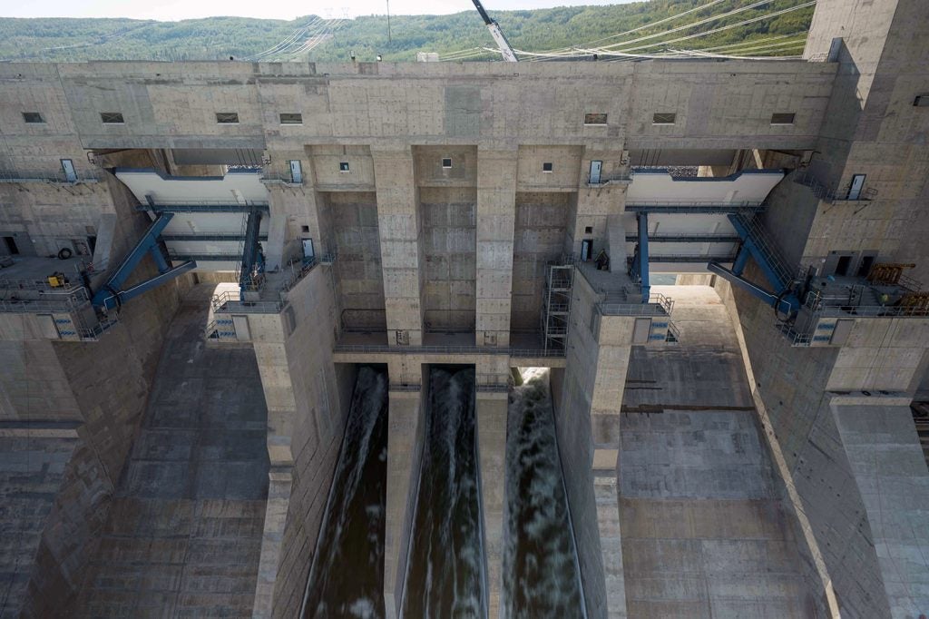
Site C civil works and dam configuration
The core dam structure is an earthfill embankment approximately 1,050 m in crest length and about 60 m in height above the riverbed.
The design comprises:
- A central impervious core keyed to shale bedrock.
- A grout curtain beneath the core trench floor to reduce seepage.
- Filter zones adjacent to the core, and gravel drains on the downstream shell.
- Outer shells consisting of coarser sands and gravels.
On the southern (right) bank, an 800 m long roller-compacted concrete (RCC) buttress forms part of the foundation/abutment scheme, enhancing seismic and structural stability of the valley wall where geotechnical conditions were weaker.
Temporary works included two cofferdams and twin diversion tunnels. The diversion tunnels allowed the Peace River flow to be rerouted so that dam construction could proceed in a dry channel. The approximate dimensions: two tunnels ~700–800 m in length, diameter ~10–12m.
This combination of earthfill dam plus RCC buttress is an engineering response to the valley geology, flood hazard, seismic loading and the need to minimize local storage volume (leveraging upstream storage) while achieving high energy yield.
Because Site C benefits from upstream water regulation (primarily via the Williston Reservoir at the W.A.C. Bennett Dam), its local reservoir is relatively modest but long. The impoundment is about 83km in length.
Maximum water depth near the dam is in the order of 50 m; further upstream, near Halfway River and Hudson’s Hope, depths decline to ~36m and ~18m respectively.
The aim is to capture regulated flows from upstream rather than rely on large local storage. This enables a high-capacity plant with comparatively smaller inundation area (5,550 ha) for the annual energy output.
Practically, the gross hydraulic head is aligned with the dam height (about 60 m) plus any additional drop from intake to tailwater. Thus, the hydraulic regime is a “mid-head” one by hydropower classification, and design choices (e.g., turbine type, penstock sizing) reflect that.
Hydraulic design
The powerhouse houses six units; each unit is fed by a dedicated steel penstock of approximately 80 m in length and diameter roughly 10 m. Procurement documentation indicates segmentation of the penstocks (for example, 14 welded sections per penstock) and transition pieces into the turbine intake.
Intake gates are vertical‐lift type, with maintenance gates and shut-off gates provided. The penstock and intake geometry were sized to control approach flow velocities, mitigate cavitation risk, and avoid redirection turbulence.
On the right abutment, an approach channel length of about 800m, depth up to 24m and width exceeding 200m was required to deliver water to the intake under controlled hydraulics. Modelled flows (including PMF – probable maximum flood) were constrained so that maximum velocities remain below ~5 m/s and typical generation flows around ~1m/sec.
The spillway complex was designed to accommodate extremely high flood flows. Dissipation structures, piers, and the conversion of diversion tunnels to controlled orifice flows during reservoir filling all played roles in the hydraulic design. The diversion tunnel orifices provide additional capacity for energy dissipation during early filling.
Hydraulic modelling ensured acceptable tailwater levels, draft tube outlet configurations and minimal downstream scour risk. The design ensures the turbine tailrace elevation remains stable under varying flow and reservoir conditions, and the transition into the Peace River is managed with erosion protection.
Turbine-generator package
The main electromechanical contract was awarded to Voith Hydro. The specification: six vertical-axis Francis turbines, each rated at ~183 MW giving an aggregate capacity ~1,100MW.
The vertical Francis configuration was selected because of the mid-head (~60m) regime combined with relatively large flows (multiple units). These turbines provide wide-range efficiency, adaptability to varying flow regimes (given upstream regulation) and robust dynamic response. Each synchronous generator is matched to the turbine output and connected via high‐voltage step‐up on site.
Auxiliary systems include excitation and governor controls, remote monitoring and protection systems complying with utility standard (industrial grid connection). The integration of six units in one powerhouse required careful load sharing, sequence control and unit synchronisation management to ensure smooth commissioning and full plant operation.
Power output from each generator is collected in the powerhouse and stepped up to 500 kV on-site (typically via step-up transformers). A new Site C 500 kV substation was constructed, and two new 500 kV transmission circuits (about 75 km in length) connect to the Peace Canyon switchyard.
The transmission system includes delta-type steel towers, gas insulated switchgear (GIS) at Peace Canyon, and short interconnecting lines within the powerhouse/substation complex (~1 km). The size of the transmission path is designed to carry full output of the plant and meet bulk power system reliability criteria (including contingency events, N-1 planning and stabilisation of the grid tied to British Columbia’s bulk system).
Ancillary systems at the substation and generation complex (e.g., SCADA, protective relays, reactive power compensation) are sized to follow the dynamic behaviour of the plant: i.e., ramping large machines, synchronising multiple units, seasonal regulation of flows from upstream reservoirs and plant startup/shutdown sequences.
Construction challenges and timeline
Construction began in 2015. Major challenges included the geotechnical complexity on the south bank (weak bedding planes, shears and isostatic rebound issues) which required the RCC buttress, slope stabilisation, deep excavations and detailed rock assessments.
River diversion via twin tunnels, cofferdams and temporary works had to be sequenced carefully to maintain environmental minimum flows, avoid delay of civil works and fit within local constraints (weather, remote location, supply logistics). Earthfill placement involved the movement of millions of cubic metres of material, careful instrumentation and quality assurance (core trench, filter zones, gravel drains).
The hydraulic modelling (physical and CFD) of the approach channel and spillway was extensive due to the unusual valley geometry and oblique intake orientations. Construction timing was affected by supply-chain constraints, labour availability and site access logistics in a remote region. Final cost estimated around C$16 billion and schedule extended somewhat from original plan.
Commissioning the Site C Dam project
The first generating unit entered service in October 2024. Units came online sequentially through the next 10 months. On August 9, 2025 the sixth and final unit was commissioned and the project declared fully operational.
With all six units in service, Site C is now serving the grid with its full design capacity. The remaining work (paving, access roads, tunnel backfill, revegetation, final equipment commissioning/deficiencies) continues in a post-commercial stage.
Operational protocols include coordination with the upstream reservoirs (W.A.C. Bennett and Peace Canyon) to optimise flow releases, capture peak-demand periods, meet environmental flow obligations downstream, and take advantage of the regulated flow potential. The plant is expected to provide reliable, low-carbon, dispatchable generation for many decades (100-year lifespan design is cited).


