

Hydropower facilities, dams and reservoirs increasingly face operational risks from floating debris, uncontrolled vessel access and environmental contamination. Flood events, seasonal ice movement, timber transport and storm runoff can inroduce large volumes of driftwood and waste into intake zones, spillways, and sensitive hydraulic structures. If unmanaged, this material may obstruct water flow, damage turbines, increase abrasion of concrete surfaces, or compromise safety zones near critical infrastructure.
Floating barrier systems provide an effective civil-engineering solution to these challenges. While such systems are sometimes associated with maritime security, their primary value in inland and coastal water power applications lies in controlled debris interception, zone demarcation, and long-term protection of hydraulic assets. In ECONAD we have been engineering, testing and manufacturing booms since the establishment in 1991. Our technologies have been using as for oil spill response operations as for civil and security protections.
With production facilities in Eastern Europe and operational projects across ports, rivers, and industrial water facilities, the company has developed a range of modular floating barriers adapted for both coastal and inland water applications.
Our engineering team combines hydrodynamic modelling, material science, and field testing to tailor barrier systems to site-specific conditions, including extreme weather environments and complex hydraulic regimes. Nowadays there are two categories of floating barriers which can be used in dam and reservoir environments: heavy-duty protective containment booms for debris interception and trespassing prevention and high-visibility demarcation barriers for controlled water zoning. Protective floating barriers designed for hydropower and reservoir applications typically consist of modular sections connected into continuous floating lines. A standard barrier module ranges from 3 to 10m in length, allowing flexible system configuration depending on the width of the protected area and local hydrodynamic conditions.
Structure and profile
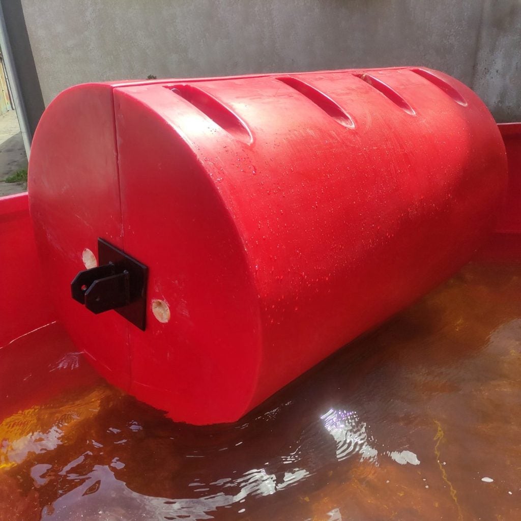
A typical module incorporates:
- A cylindrical or multi-chamber float (diameter 400–800mm, length from 1500-3500mm), providing buoyancy and stability
- A vertical flexible skirt extending 0.6–1.5m below the waterline (optional)
- A reinforced tension member (steel cable or polyester rope) integrated along the top or internal axis
- Connection flanges or quick-lock couplings at both ends
- Optional ballast chain in the lower edge of the skirt for improved vertical stability or the anchorage
The resulting profile allows the boom to ride over small waves while maintaining sufficient submerged depth to intercept floating and semi-submerged debris.
Materials
Modern protective booms are commonly manufactured from:
- PE tubes or plastic for floaters
- Marine-grade aluminium or hot-dip galvanized steel connectors
- Closed-cell polyethylene or polyurethane foamed core
- UV- and hydrocarbon-resistant coatings for metal part for extended service life
These materials are selected to withstand prolonged exposure to ultraviolet radiation, temperature fluctuations from –30°C to +50°C, mechanical abrasion, and intermittent contact with oil or industrial pollutants.
Anchoring and installation
Anchoring systems are customised for site conditions and may include:
- Concrete anchor blocks (widely used)
- Steel piles (depending on location)
- Bank-mounted tension cables
- Elastic mooring compensators to absorb dynamic loads
Barriers can be installed in straight-diagonal or curved lines, V-shaped debris deflection configurations, or semi-circular intake protection layouts.
Demarcation and controlled-access barriers
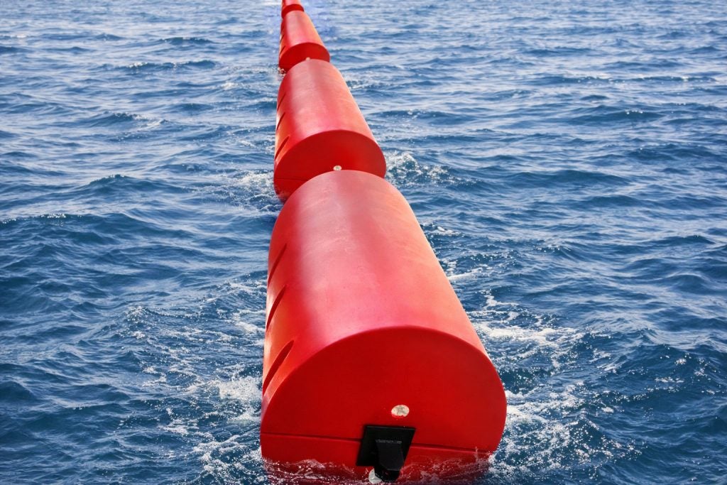
A second category of floating barrier systems is designed primarily for visual demarcation and controlled water zoning. These systems feature:
- Larger-diameter floats (typically 600–1,000 mm)
- Bright coloration (yellow, orange, or red)
- Integrated reflective strips and navigation lights
- Optional signage mounts or sensor brackets
Although lighter than debris-containment systems, these barriers still provide moderate interception capability for plastics, vegetation, and light timber.
In dam and reservoir environments, demarcation barriers are commonly used to:
- Mark restricted zones near intakes and spillways
- Separate operational and recreational areas
- Indicate environmentally protected water zones
- Support monitoring infrastructure
Their secondary function of debris interception further reduces material accumulation near sensitive hydraulic equipment.
Operational principles and application
Floating barrier systems operate by combining passive hydrodynamic deflection with physical interception.
As water currents transport debris downstream, the floater or the submerged skirt creates drag that redirects material toward collection zones or riverbanks. Larger objects are retained by the float line, while smaller debris accumulates along the barrier until scheduled removal.
For dam operators, this approach offers several advantages:
- Reduced mechanical load on trash racks and intake screens
- Lower maintenance frequency for turbines and gates
- Improved water flow predictability
- Enhanced operational safety for inspection crews
- Protection of environmentally sensitive shorelines
Typical application areas include:
- Upstream of hydropower intakes
- Reservoir inflow zones
- Spillway approaches
- Navigation locks
- Cooling water intakes for thermal power stations
- Flood-prone river sections above dams
Field experience
River border between Ukraine and Transnistria
A barrier installation was implemented on a wide river section forming a natural border between Ukraine and Transnistria. The area experiences seasonal floods with debris, and and frequent unauthorised small-vessel crossings. The barrier system was configured in a shallow V-shape to guide debris toward a designated collection bank. During peak spring runoff, the installation successfully intercepted large volumes of branches and tree trunks, preventing their entry into downstream hydraulic structures and bridge zones.
Local water management authorities noted stable positioning even under elevated current velocities and reported minimal maintenance requirements beyond periodic debris removal.
Mountain river debris protection
In a mountainous river catchment, floating barriers were used to protect a small reservoir from storm-driven debris flows and common waste. This environment posed unique challenges due to:
- High flow velocities
- Sudden water level changes
- Large, irregular wooden debris and general waste
A reinforced barrier model with additional tension cables and shallow skirts was selected. During multiple storm events, the system retained substantial volumes of organic material while remaining structurally intact.
Post-event inspections confirmed no connector failures or significant float deformation, validating the suitability of modular floating barriers even in aggressive hydrological conditions.
Ukrainian seaports
Protective floating barriers were deployed in multiple Ukrainian commercial ports to manage driftwood and floating waste entering harbor basins and approach channels.
The systems were installed in segmented lines across secondary inlets and near cargo handling zones. Over two seasonal cycles, port authorities reported:
- A reduction of floating debris accumulation by approximately 65–75%
- Improved accessibility of berths after storm events
- Decreased downtime for mechanical cleaning operations
- No structural damage to the barriers despite frequent vessel wash and winter ice fragments
Technical considerations
For long-term dam and reservoir applications, several design parameters are critical:
- Hydrodynamic loading calculations to ensure adequate tensile strength
- Redundancy in mooring lines to prevent failure under asymmetric loads
- Ice-pressure resistance for cold climates
- Maintenance accessibility, including safe work zones for debris removal
- Environmental compatibility, avoiding harmful leaching or wildlife entanglement
When properly engineered, floating barrier systems typically achieve service lives of 10–15 years with routine inspection and component replacement.
Floating barrier systems represent a practical, cost-effective infrastructure element for protecting dams and reservoirs against debris ingress, operational disruption, and environmental impact. Beyond their traditional security associations, these systems play a vital civil-engineering role in modern water power management.


