A risky business
7 May 2010The US Bureau of Reclamation (USBR) has developed a procedure using risk analysis to evaluate dams for loading conditions, including seismic loads. Here Larry Nuss, Barbara Mills-Bria and Phoebe Percell give a detailed example of this procedure for USBR’s East Canyon dam in Utah
A number of potential failure modes may be considered for the seismic loading of structures such as an arch dam. The process described in this article would be used in estimating the probability of failure for each potential failure mode. Risk analysis has proven to be a very effective tool for decision making at the US Bureau of Reclamation. Detailed analyses and field exploration form the basis of all estimates that are made, helping to ensure that the risk analysis is reliable.
Complicated design
East Canyon dam, located in a very narrow, steep walled canyon, is a double-curvature, thin arch concrete structure with a structural height of 79m and a crest length of 133m. The spillway is an uncontrolled overflow-type structure constructed in the crest of the dam adjacent to the left abutment. Two low angle continuous discontinuities, a vertical side joint and an assumed release plane define a potentially movable block in the foundation.
The presence of an old dam, the topography, and the need to maintain a reservoir during construction complicated the design of this new concrete arch dam. In the final design only 2m separated the new and the old concrete dams at the closest point.
During construction, the stability of the existing dam was assured by careful control of blasting, checking the structural behavior of the dam through measurements, and requiring that the undercut portion of abutment rock at the old dam be supported by concrete placements in the new dam prior to allowing appreciable storage behind the old dam.
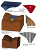
A finite element model was created, which included the critical foundation blocks, the current dam, the 1915 arch dam (immediately upstream from the current dam) and the reservoir. An unbounded lift line was modelled in the thrust block. Two foundation rock blocks were modelled.
The analyses examined the behavior of the dam and foundation block stability using a coupled analysis under seismic loads. The finite element programme LS-DYNA was used for the analysis. It consisted of 455,400 nodes and 423,100 solid eight-noded brick elements. All ten dam monoliths and the thrust block on the right abutment were modelled.
The concrete and rock material properties used in the nonlinear analyses were based on calibrations using laboratory test values and forced-vibration testing performed at the dam. From the forced vibration testing, the natural frequencies of the dam and damping factors were also estimated. Down-hole geophysical testing was performed to determine the in-situ velocity and dynamic deformation moduli of the concrete and foundation.
The material properties used in the finite element model included Young’s moduli, densities, and Poisson’s ratios for the rock and the concrete. In addition, compressive strengths and tensile strengths were determined. As this structure is very thin the response to temperature loads is important. For this reason analyses were performed for summer, winter and average temperatures at the dam.
Gravity loads were applied over time and the model was allowed to reach a steady-state prior to application of the dynamic loads.
Uplift pressures acting perpendicular to the rock foundation joints and bedding plane based on piezometer readings were applied as pressure loads.
For these analyses, ground motions, obtained from the Geophysics and Seisomology Group, corresponded to the median annual exceedence probabilities (AEP) of 1/5,000yr, 1/10,000yr and 1/50,000yr. A suite of three-component ground motions was provided for each AEP, with motions provided in upstream-downstream, cross-canyon, and vertical components. Contact surfaces were used to model the interaction in the contraction joints between:
• The foundation rock block and the surrounding foundation.
• The dam monoliths and the foundation.
• The water and the dam and the water and the foundation.
• The two sections of the reservoir (one upstream and one downstream of the old dam).
The dynamic finite element analysis of the dam-foundation-reservoir system was subjected to various combinations of temperature, reservoir elevation and seismic loads.
The results from these analyses were used by a team consisting of a geologist, geotechnical engineers, structural engineers, and a facilitator to determine the potential risks associated with this structure.
Risk analysis is used as a decision making tool by the USBR dam safety office. All of the analyses and field work previously discussed are used to estimate the likelihood of events occurring that lead to a potential failure of the structure or foundation. A possible event sequence that would be considered for East Canyon dam is the following:
• Reservoir water surface elevation.
• Seismic load ranges.
• Response of concrete dam is sufficient to cause horizontal cracking in the dam.
• Response of concrete dam is sufficient to cause diagonal/vertical cracking in the dam.
• Cracks are continuous through the section of the dam.
• Isolated blocks formed in the dam rotate and are released downstream initiating uncontrolled release of the reservoir.
Since there have been no known arch dam failures as a result of earthquake shaking, there is no direct empirical evidence to indicate how an arch dam would structurally fail under this type of loading. Therefore, shake table model studies have been performed to gain some insight into what might happen (Harris, 2002).
In the models, an attempt was made to maintain material similitude between the model material and typical dam concrete. The model foundation and abutments were essentially rigid (built of conventional concrete). Some models included contraction joints and/or weak lift joints by inserting plastic sheets in the modeling material as it was placed.
However, it was not possible to maintain similitude with the reservoir, and water was used in the models. Therefore, it is difficult to conclude anything about the level and duration of shaking that could lead to failure from the models. But the failure modes were relatively consistent, and provide some indication as to how an arch dam might fail under earthquake shaking. In these tests:
• Failure initiated by horizontal (cantilever) cracking across the lower central portion of the dam.
• This was followed by diagonal cracking parallel to the abutments.
• The cracking propagated through the model forming isolated blocks within the dam.
• Eventually, the isolated blocks rotated and swung downstream releasing the reservoir.
With this description forming the sequence of events for potential failure, an event tree is used to estimate each step in the potential failure process. It is necessary to perform structural analyses, such as discussed earlier, at various earthquake loading levels to evaluate the potential for each subsequent step in the tree.
If the reservoir fluctuates significantly over the course of a year, and the response changes dramatically with reservoir elevation, it may also be necessary to include different reservoir load ranges (with the appropriate temperature conditions) in the tree as well. Similarly, if the concrete temperature conditions control the initial static stress conditions, and the results are highly sensitive to these initial stresses, it may be more appropriate to set up the tree with the various temperature conditions (and corresponding reservoir elevations).
For each reservoir and seismic load range that is established for the estimating process, the likelihood of cracking at various orientations (over significant areas – not just localised cracking), and cracking through the dam body must be estimated. The best approach for this is to perform three-dimensional dynamic time-history finite element studies.
Examination of output stresses and their duration indicates whether the estimated dynamic tensile strength of the concrete is exceeded at the dam faces during seismic response. The orientation of the principal stresses can be used to gauge the likely crack directions for various times during the earthquake loading. As the amplitude of these stresses and number of excursions above the tensile strength increase, the likelihood of cracking also increases.
One or two excursions above the tensile strength do not necessarily equate to a high likelihood of cracking, particularly if the amplitudes do not exceed the tensile strength by a significant amount. If contraction joints are modeled in a nonlinear analysis, it is possible that diagonal principal stresses will not develop due to ‘opening’ of the contraction joints. In this case, the potential for ‘stair-stepped’ cracking roughly parallel to the abutments must be assessed.
If the shaking is severe enough, the cracking can extend through the structure forming an adverse cracking pattern. This is typically evaluated by examining the magnitude and duration of tensile stresses that exceed the dynamic concrete tensile strength on both the upstream and downstream faces. Again, judgment is required on the likelihood of cracking through the structure at various earthquake (and possibly reservoir/temperature) levels.
If the arch cracks all the way through, the likelihood of isolated blocks rotating and displacing downstream is next estimated. Information typically used to make this assessment includes the duration of strong shaking and stresses. The primary questions to be asked are: How likely is it that there will be sufficient energy left in the earthquake to move blocks downstream after they have cracked through?; How likely is it that the cracking pattern will be adverse enough that the portion of the dam isolated by the cracking will be unstable statically following the shaking?
For the latter to occur, the ‘semicircular’ cracking pattern that typically results in the upper part of the dam must be smaller on the upstream face than the downstream face, such that the cracks diverge in the downstream direction. It would be assumed that if the potential failure mode progressed to this point, a breach and uncontrolled release of the reservoir would result. The estimates made for each of these nodes is combined to an estimate of the probability of failure for the given potential failure mode.
Larry Nuss, Technical Specialist at the US Bureau of Reclamation, Email:Lnuss@usbr.gov; Barbara Mills-Bria, Structural Engineer, bmillsbria@usbr.gov; Phoebe Percell, Structural Engineer, ppercell@usbr.gov