Constructing Kannaviou dam
15 July 2004Demos Antoniou, Paul Legg and Dimitris Glavas discuss the main issues related to the construction of Kannaviou dam, the first CFRD dam in Cyprus.
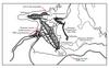
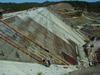
KANNAVIOU dam is located on the Ezousa river, about 40km from Paphos in north-west Cyprus. It is owned by the Government of Cyprus and the engineering and design of the project was developed by KBR (contracting as Howard Humphreys & Partners, UK). The contractor is AEGEK of Greece in a joint venture with Iacovou Brothers and Cybarco from Cyprus. Work began in September 2000 and is expected to finish in June 2005. About 70% of the project is currently completed.
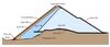
The dam is a concrete face rockfill dam (CFRD), with maximum height of 75m, crest length of 600m and a volume of rockfill of 1,800,000m3. The upstream slope has a 1V:1.4H inclination and the downstream slope is 1V:1.7H. Kannaviou is the first CFRD dam constructed in Cyprus.
The foundation of the dam is essentially on pillow lavas of the Troodos formations. The upstream face is supported at the perimeter base with a reinforced concrete plinth, which is founded on sound rock of grade II to III and the rest of the embankment is founded on either rock or alluvium. In the river bed, the layer of existing alluvium was removed below the upstream concrete slab in a strip equivalent to the base width of Zone 3B. In the remaining area, the alluvium was incorporated in the dam.
The reinforced concrete plinth is 0.5m thick and 5–11.2m wide. It is anchored to the foundation with 40mm diameter high yield bars. The plinth forms a platform for the curtain grouting which is upstream of the embankment. The line of curtain grouting under the plinth contains about 500 grouting holes of depth 40m. Upstream and downstream of the curtain grouting, there are two lines of consolidation grouting, with about 1000 holes of depth 10m. The grouting holes were initially spaced at 3m centres. The grouting works, currently in progress, are about 60% complete. Grout takes are generally low, as expected from the preliminary hole water test results. The grouting works are carried out using the GIN method; GIN numbers used are 500–2000 and pressures vary between 10–30 bars depending on the location, depth and quality of the rock. A fully automated uplift monitoring system has been devised to ensure that there is no vertical movement of the plinth during grouting. The grout pumps are automatically switched off if the system detects movements greater than 1mm. This is the first time this method has been used in dam construction in Cyprus.
The upstream slab has a total area of 42,000m2 and thickness which varies from 0.3m at the crest to 0.45m at the deepest section as given by the formula: d=0.3+0.002H. The concrete of the slab has a 28-day strength of 25MPa, maximum aggregate diameter of 40mm and an average of 350kg/m3 of pozzolanic cement. Reinforcing of 0.4% was adopted in each direction in the centre of the slab. The slabs will be poured using a 15m wide slip form.
The sealing of the perimeter joint consists of:
• Copper waterstop, installed in the base of the slab;
• Seal of asphalt mastic igas, at the top of the joint and;
• A layer of silty (Zone 1S) on the perimeter joint, protected on top with soft rock soil fill.
The sealing of the vertical joints between panels in the river bed section (compression joints) consisted of a copper waterstop installed in the base. In the joints between panels of the abutments (tension joints), a seal of asphalt mastic covered with a fabric rubber strip was used in addition to the copper waterstop.
Zoning of rockfill
Rockfill for the embankment is selected from two designated quarries; A which is a diabase quarry and B, a soft rock pillow lava quarry. The quarries are located within the reservoir area.
The embankment is divided into materials of zones 2A, 2B, 3A, 3B, 3C and 3D.
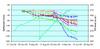
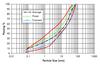
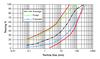
• Zone 2B, under the upstream slab, has a width of 4m. It consists of screened alluvial extracted from the river bed, with maximum size 75mm and fines up to 8% (0.063mm). It was compacted in 0.4m layers with six passes of 10t vibratory roller. After the removal of the excess material beyond the design line, the compaction of the slope was carried out with four passes of a vibrating plate. After the compaction, the slope was protected with a layer of 50mm shotcrete.
• Zone 3B corresponds to the upstream section of the dam. The material consists of sound rockfill taken from quarry A, spread and compacted in 0.8m thick layers with six passes of 19t vibratory roller. During the unloading and spreading, water was added at a ratio of 100l/m3 of rockfill.
• Zone 3A is a transition to Zone 3B. It has a width of 4m. This zone is of the same material as Zone 3B with sizes greater than 200mm removed, spread in 0.4m layers and compacted with six passes of 10t vibratory roller. The placement of zones 2B and 3A always followed that of Zone 3B, with removal of the segregated materials in the contact between the two zones.
• Zone 3C, corresponding to the downstream portion of the dam, was built mostly with pillow lava material produced from the excavations and quarry B. This rockfill was spread and compacted in 0.5m layers with water addition up to 12% and six passes of 19t vibratory roller.
• Zone 2A, with 2m width and 3m height, is located immediately downstream from the plinth. The material placed along the perimetric joint, is produced from screened alluvial from the river bed below 20mm and with fines up to 10%.
• Zone 3D is the downstream slope protection layer 3m wide and it comprises large river alluvial cobbles or crushed diabase with maximum size up to 300mm.
Stages of construction
The dam was built in two stages in order to meet the schedule, the requirements for plant utilisation and use of materials. The diversion of the river through the tunnel started before the winter of 2001-2002 and following construction of the two cofferdams in the main and side valleys. The main cofferdam included a permanent cut off wall, through the 15m deep alluvium, which was achieved with jet grouting methods.
Construction of the dam began with the embankment on the downstream part, with direct placement of the material from the excavations of the left abutment. These portions of the dam were built keeping a distance of 20–30m from the final upstream slope of the dam, in order to avoid disruption of the construction of the plinth and the upstream transitions at this construction stage. About 400,000m3 were placed in the first construction stage.
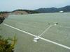
Construction of the second stage started after the completion of the plinth in the main and side valley river beds. The whole of the embankment was completed just before the end of June 2004. Works have already started for the placing of the upstream slab.
Investigation / control of construction
Geotechnical investigations of the foundations for the whole of the dam included about 700m of core drilling and 40 permeability tests with the cores logged and tested for strength. The geological appreciation has been developed using all the available information to assist in the final design of the plinth and also to evaluate the subsequent results of the grouting works.
The investigations included rock mechanics tests carried out during the basic design, axial compression tests and shearing tests of discontinuities.
Quality control of the rockfill and transition zones included in-situ density tests, permeability tests, gradings and tests for the mechanical qualities of the materials. The average measured densities were: 2.33Mg/m3 for zone 2B material, 2.3Mg/m3 for zone 3A, 2.24Mg/m3 for zone 3B and 2.16Mg/m3 for zone 3C.
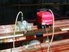
Strict control of the copper water stop brazing was carried out, with visual inspection, penetrability tests and vacuum tests of 0.3 bars vacuum. For this purpose vacuum boxes were developed on site and have been used very successfully.
Dam behaviour
The behaviour of the dam during construction was monitored with instruments installed in three cross sectional locations. Surface monuments were installed along two levels on the downstream slope of the embankment. Vertical displacements in the embankment are measured with hydraulic settlement cells and the water levels in the dam foundation with standpipe and vibrating wire piezometers. More vibrating wire joint meters will be installed along the perimetric joint in order to measure the movement of this joint.
The maximum recorded settlement values at completion of the embankment were 160mm in zone 3B and 200mm in zone 3C. The moduli of deformability of zones 3B and 3C, determined from the measured settlement and the stresses corresponding to the weight of the overlying layers were 90MPa and 50MPa respectively.
From the survey monuments installed on the downstream slope of the embankment, the horizontal movements were of the order of 10–20 mm in both directions and the settlements up to 50mm.
Author Info:
Demos Antoniou is with the Water Development Department Government of Cyprus, Paul Legg is with the KBR and Dimitris Glavas is with AEGEK
| Table 1: KANNAVIOU DAM - DESCRIPTION OF WORKS |
| Type – Concrete faced embankment with body of zoned basal group and pillow lava rockfill and filters and drains of processed alluvium. Hydrological data – Catchment area: approximately 56km2; Mean annual rainfall on area: 770mm; Total annual inflow into reservoir: 9.1Mm3; Reservoir capacity: 18Mm3 Dimension – Crest elevation: 419.1m AMSL; Original river bed at toe: 363m AMSL; Base of alluvium: 342m AMSL; Maximum height above river bed: 56m; Volume of fill (all materials): 1,800,000m3 River Diversion Works – Horseshoe shaped concrete lined tunnel and culvert; Diameter: 3.3m; Tunnel length: 340m; Culvert length: 30m; Cofferdam crest level: 376m AMSL; Capacity: 43m3/sec (50yr flood) Inlet/Outlet Works – Concrete draw-off Tower connected to river diversion tunnel; Diameter: 4.3m; Height: 54m; Pipework diameter: 600mm, 700mm, 1000mm; Operational drawoff levels: 408m, 395m, 377.5m AMSL; Operational drawoff: 1.0m3/sec; Bottom outlet drawoff level: 376m AMSL; Bottom outlet: 8m3/sec Spillway – Uncontrolled overflow concrete weir; Crest elevation: 414.0m AMSL; Crest length: 40m, into 10m wide chute; Routed discharge: 780m3/sec Foundation Treatment – Removal of full depth of alluvium, to found toe plinth on rock (requiring pumped wells and diaphragm wall under upstream cofferdam); Single row curtain maximum depth 40m; Two rows blanket grouting depth 10m |