Damage limitation – a new spillway aerator
6 June 2008Mualla Ozturk, Mehmet Cihan Aydin and Seckin Aydin present a detailed report on the design of a new spillway aerator developed to prevent cavitation damage
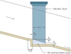
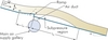
High velocity flows over spillways of high-head dams may cause cavitation due to excessive decreases in pressure in local regions. Cavitation over the chute bottom causes erosion of the concrete surface, causing serious damage over time. Today there are only a few approaches for preventing cavitation damage. The most effective is to induce air entrainment into flow using aerators. In a conventional aerator, the water jet is deflected from the chute bottom by a step and/or ramp, and the cavity subpressure region which is under atmospheric pressure is produced beneath the water jet. The subpressure beneath the water jet plays an important role in the performance and efficiency of the aerator. Air is entrained into the flow through side ducts due to the pressure difference. These types of aerator with a natural aeration mechanism work quite efficiently. However, if the aerator cavity subpressures decrease too much, it may cause submergence of the aerator. The subpressure below the water jet may decrease excessively, meaning the nondimensional step and ramp height may be under the determined limits, the cross-section of the air duct is insufficient or the chute channel is too wide. Because of the excessive reduction of the pressure under the jet, the lower nappe of the water jet may adhere to the bottom, submerging the aerator. This condition significantly decreases the aerator performance. However, in very wide spillway chutes, aerators cannot provide a uniform air distribution across the chute even if it is not submerged completely.
Rutschmann et al [1] noted that it was desirable to minimise the aerator cavity subpressure to achieve the greatest possible air discharge and as uniform air distribution as possible. Kells and Smith [2] concluded that the air supply system had to be sufficiently large to minimise the possibility of any adverse effect of high-velocity air flow. Chanson [3] concluded that a submerged aerator might act as a cavitation generator, even at low Froude numbers, and pointed out that special attention must be given to the aerator cavity subpressure when designing an aerator. If the air demand created by the aerator greatly exceeds the capacity of the air supply system, with attendant reduction in cavity subpressure, it is suggested that the water jet may collapse and fill the aerator [4]. The performance of a submerged aerator is quite low and it does not provide a uniform air mixture. In order to provide an air distribution as uniform as possible and a maximum air discharge through the air supply duct, the cavity subpressure differences of the aerator should be minimised.
According to Chanson [5], at low Froude numbers or for low channel slopes the aerator is submerged when the air discharge is zero. A submerged aerator condition was also defined by Pinto et al. [6]. They emphasized that a submerged aerator acts as an obstacle to air entrainment and should be prevented. Rutschmann [7] applied only a ramp and determined that a ramp with a low slope can be more effective for high subpressures, but the aerator can still be submerged. Rutschmann and Hager [8] noted that the aerator is submerged when Froude number is Fr<6.
A well-designed aerator device should not be submerged and it should provide a uniform air distribution across the spillway chute [9]. In this study, a new aerator type – a bottom-inlet aerator – is suggested which may help combat these problems while providing better aeration at low froude numbers.
Method
In this study, the numerical analyses have been carried out by means of Fluent, a computational fluid dynamics software package to simulate fluid flow problems. It uses the finite-volume method to solve the governing equations for a fluid. Geometry and grid generation is done using Gambit which is the preprocessor bundled with Fluent.
In the numerical solutions, a 3D multiphase model (Algebraic Slip Mixture Model) and standard k-´ turbulence model were used. The standard k-e model is a semi-empirical model based on model transport equations for the turbulence kinetic energy (k) and its dissipation rate (´). The model transport equation for k is derived from the exact equation, while the model transport equation for ´ was obtained using physical reasoning and bears little resemblance to its mathematically exact counterpart.
The algebraic slip mixture model was used in the numerical solutions. This model does not assume that there is an interface between two immiscible phases; it allows the phases to be interpenetrating. Moreover, while allowing the two phases to move at different velocities, the model can solve the continuity equation and the momentum equation for the mixture [10].
Verification of the method
In all the numerical solutions, the iterative convergence at every time step was checked and achieved with at least three orders of magnitude decrease in normalized residuals for each equation [11].
The different turbulence models are used to determine sensitivity of results to turbulence model. The results with standard k- ´ and RSM are very close, but RSM takes more CPU time on a per-iteration because of seven equations. For this reason, in the CFD analyses, the standard k- ´ is used as the turbulence model.
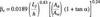
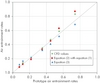
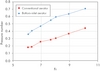
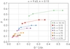
In order to verify the method, the data derived from Fluent CFD are compared with the prototype data and the results of empirical equations. The prototype data of Foz do Areia dam spillway aerator no:1 in Brazil presented by Pinto [12] and some empirical relationships are considered in the comparisons. Kokpinar and Gogus [13] presented the following empirical relationship relevant to air entrainment rate with a correlation coefficient of 0.90.

where ß is air entrainment rate, Lj is jet length (m), h is flow depth (m), Aa is entrance area of air supply duct (m2), Aw is water flow area before the aerator (m2), and a is slope angle of spillway chute. The subscript c indicates a calculated value. They also proposed the following expression to define scale effects between prototype and calculated values from Equation (1) based on their laboratory tests

where ? and e are experimental constants, the subscripts p and e indicate prototype and experimental model value respectively.
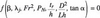
Equation (3) was presented by Pinto [12] for the prototype data from Foz do Areia, Emborcacao, Amaluza, Colbun and Terbela Dams, as:


where, Fr is Froude number, c is discharge coefficient (as used in a conventional orifice flow equation), and B is width of spillway chute (m).
Figure 2 shows the results of CFD analysis by Fluent are in reasonable agreement with prototype data and Equations (1) and (3).
New aerator type
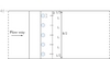
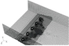
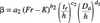
The new aerator type suggested in this paper is referred to as bottom-inlet aerator (Figure 3). Although the working principle of this aerator is not completely different from conventional aerators, it provides a more uniform air mixture at the cross-section of flow, particularly very wide flow. The suggested aerator in this study consists of a ramp, the circular air ducts arranged along the spillway chute width downstream of the ramp on the chute bottom, and a main air gallery supply. This gallery can be opened to the atmosphere through the side walls. The ramp creates a subpressure region by lifting up the high velocity water-jet above the chute bottom. A small ramp is sufficient for this. The air is entrained into flow due to the cavity subpressure via the air ducts and main gallery.
In conventional aerator types, because the energy losses occur along the chute width below the jet, the regions near the side wall of the chute are aerated more than the middle parts. The authors aim to provide a uniform air mixture throughout the whole flow cross-section and to balance the subpressure distributions below the water jet by means of the bottom-inlet aerator, diminishing the risk of submergence significantly.
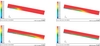
In Figure 4, the bottom-inlet aerator and a conventional aerator were compared at the same flow condition and the same total air duct cross sectional area [14]. It is determined that the bottom-inlet aerators provide a better aeration performance and a more uniform air mixture, especially in wide spillway chutes.
Dimensional analysis
As a result of dimensional analysis, the following relation has been obtained in terms of nondimensional parameters:

Where tr is ramp height (m), D is diameter of the aeration ducts (m), L is distance between the ducts (m), ß is defined as the ratio of the flow rate of air entrained through aeration ducts to the discharge of water, i.e., Qa/Qw. Re is the Reynolds number defined as the ratio of the inertia forces to the viscous forces (?whU2w/µw), Fr is the Froude number defined as the ratio of the inertia forces to the force of gravity (Uw/(gh)1/2), E is the Euler number defined as the ratio of the pressure forces to the inertia forces (?wU2w/?p), We is the Weber number representing the ratio of the inertia forces to the forces of surface tension (?whU2w/ss) and ?j is the dimensionless jet length defined as the ratio of the jet length to the flow depth (Lj/h). The effects of Re and We on the air inlet phenomena is quite low and can be neglected. Several researchers such as Pinto et al [15] Pinto [16], Rutchmann and Hager [8], Chanson [5, 17], Kökpinar and Gogus [13] pointed out that Re and We do not have an important effect on air entrainment if they are higher than the obtained values, and assumed that they can be neglected. However, in small scale model experiments, neglecting Re and We can cause serious scale effects. Since this study uses computer models with real dimensions, there will not be any scale effect. Therefore, the effects of Re and We can be deleted from Equation (5). In order to represent pressure forces, pressure number, PN, is used instead of E. PN number has been accepted by many researchers and was first defined by Tan [18].

Where ?P is the difference between atmospheric pressure and cavity pressure below the jet, ?w is water density, g is gravitational acceleration.
The nondimensional parameter, =D2/4Lh, can be defined as the ratio of an air duct area with a diameter of D to the flow cross-section area to be supplied by a duct. By deleting the constant values, a nondimensional parameter, D2/Lh can be replaced with D/h and L/h parameters in Equation (5). This parameter is one of the important values determining the air entrainment capacity of the aerator. As a result Equation (5), which consists of nondimensional parameters, can be rewritten as follows:

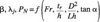
The parameters ß, ?j and PN in Equation (7) can be defined as a function of the other independent parameters as,

Model parameters
The general view of the bottom-inlet aerator model is shown in Figure 3. To decrease computation running time and finite volume number, the longitudinal symmetry of the model was considered. On the model, chute width (B=20m, due to symmetry B=10m) and the ramp angle (?=7.59°) are taken as constant. On the spillway bottom, the aerator ducts at various intervals (L) and of various diameters (D) are placed. In Table 1, some flow characteristics of the approaching flow such as unit flow discharges, flow depth, velocity and Froude number are presented. The considered values of velocity Uw are quite risky for cavitation. The flow velocity is assumed as 12-15m/sec for initiation of cavitation and an aerator is required to avoid cavitation for the velocity of 20-30m/sec [5, 17].
Three different values for the ramp height (tr) are considered as 0.10m, 0.15m, and 0.20m. The diameters (D) of the ducts row placed on the bottom are considered as 0.40m and 0.60m, and the intervals between the ducts (L) are considered as 2m and 1.67m; so, D/h values have been varied from 0.20 to 0.36. For the spillway bottom slope, three different values as a=9.65°, 14.57° and 29.68° have been selected. Therefore the effects of each variable are taken into consideration separately on the phenomenon. In the CFD analysis 252 different solutions were coducted. Regression analyses was then performed with the obtained data and some relations have been discovered.
Model and grid scheme
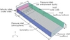
The geometry of the 3D numerical model is generated using Gambit software. A spillway chute 30m long, 20m wide and 3.5m high was considered. To observe the flow jet and the air mixing downstream of the aerator, a chute of 26m is considered from the end of the ramp. For a maximum water depth of 2.5m, the side wall height is selected as 3.5m.
The numerical solutions were tested by the different fine and coarse grids. In order to achieve the grid independence the volume of model was meshed with approximately 250,000 hexahedral cells and the air entrainment regions are meshed by two-fold finer cells. The geometry and boundary conditions of the model are shown in Figure 5.
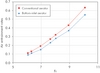
The effect of Froude number
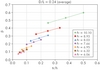
Froude number is one of the most important variables on the aeration performance. The variation of average air entrainment rate with Fr is shown in Figure 6. For all data, it is clear that the air entrainment is zero at a value of Fr. It means that below a minimum value of Fr, air entrainment cannot occur. For conventional aerators, this value is determined as Fr=5.4 by Rutchmann and Hager [8] and Fr=4.5 by Pinto [12]. For the bottom-inlet aerators in this study, a second-order equation of ß is determined with a correlation of 95.8% as:

where, for ß=0, the Fr is obtained as 4.54 – almost equal to Pinto’s [12] value.
The effect of geometry
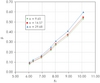
As an illustration, the effect of nondimensional ramp height, tr/h, on the aerator performance is shown in Figure 7a. The D2/Lh, which is the ratio of a unique aeration duct cross-sectional area to the flow section area supplied by this aeration duct, has an important positive effect on the aerator performance (Figure 7b). However, above a certain value (the value that supplies the air demand completely) the effect of this parameter on air entrainment will decrease. It is important to determine the minimum D/L ratio that ensures the best aeration. The chute slope has also a positive effect on air entrainment rate, but this effect is quite low (Figure 6).
Direct approach
Because of the cavity subpressures, the PN number is strictly dependent on D2/Lh parameter. For this reason, the parameter of D2/Lh can be represented by the effects of PN number. Therefore, the following nondimensional relationship that includes the all relevant parameters can be derived:

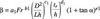
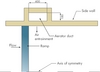
where; ai, bi, ci, di and ei are coefficients determined by the regression analysis. These coefficients were determined by performing the multiple regression analysis on 252 data points obtained from this study, and the following equation was determined with a correlation of 99.6%:

A similar equation is derived by Pinto et al [15] for conventional aerators using the prototype data as follows:

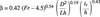
where Da = CDAa/B and CD is the discharge coefficient including the effect aeration duct for the conventional aerators. In this equation the spillway chute slope is neglected. For the bottom-inlet aerators, if the parameter of D2/Lh is defined instead of the nondimensional parameter of Da/h, a relationship can be determined as similar to Equation (12). Therefore, the coefficients of a2, b2, c2 and d2 were determined by performing a multiple regression analysis on 252 data points obtained from this study, with a correlation of 99.4%. K value in the equation was determined as K=4.5 for ß=0. According to these coefficients, the following equation similar to Equation (12) was defined:

For conventional aerators, Pinto et al. [15] stated that the effect of relative ramp height in their similar equation is quite low and can be neglected. However, in Equation (13), the effect of relative ramp height (tr/h) is more important and cannot be neglected. If it is assumed that the bottom-inlet aerators provide a uniform air mixture even for low Fr numbers as Fr<4.5, it is more appropriate to use Equation (11) instead of Equation (13). These equations are derived for the following ranges: 6.05=Fr=10.10, 0.17=tana=0.57, 0.04=tr/h=0.50, 0.032=D2/Lh=0.539, ?=7.59°.
Conclusion
This study presents a new approach for the aerators designed to prevent cavitation on dam spillways. A problem with conventional spillway aerators is that it may become submerged due to low Fr numbers and insufficient air entrainments. Particularly in wide spillway chutes, a uniform air mixture along the spillway chute width cannot be provided.
In this paper a new aerator type – the bottom-inlet aerator – has been suggested in order to overcome this situation. This aerator could provide a greater performance and better air mixture in a wide chute than conventional aerators. The multiple regression analyses were performed on 252 data points obtained from the three-dimensional CFD analysis by Fluent, and the derived equations should be used in the spillway design at the first stage. However, it is suggested that this study should be supported by extensive experimental studies.
It should be noted that the dimensions of the main aerator gallery have not been taken into consideration in this study. However as a practical rule in terms of design, the cross-sectional area of the main gallery can be taken as equal to half of the total cross-sectional area of the ducts placed on the channel bottom, in case of symmetric aeration. The bottom-inlet aerators are suggested for use in chute channels that have cavitation risk, at the low Fr number and at very wide spillways chutes.
The authors are: Mualla Oxturk, Civil Engineering Department, Firat University, Elazig, Turkey; Mehmet Cihan Aydin, Bitlis eren University, Technical Vocational School of Higher Education, Bitlis, Turkey; and Seckin Aydin, 21th Zone Directorate, State Water Works (DSI), Aydin, Turkey
NOTATIONS
Aa entrance area of air supply duct (m2)
Aw water flow area before the aerator (m2)
B width of spillway chute (m)
D diameter of the aeration ducts (m)
Fr Froude number
g gravitational acceleration (m/s2)
h approaching flow depth (m)
K a coefficient
ks boundary roughness (m)
L distance between the aeration ducts (m)
Lj jet length (m)
Lr length of ramp (m)
PN pressure number
Qa discharge of entrained air (m3/s)
qa unit air flow discharge (m3/s/m)
qw unit water flow discharge (m3/s/m)
Qw discharge of water (m3/s)
Re Reynolds number
tr ramp height (m)
Ts relative step height
ts step height (m)
Ua air velocity
Uw mean flow velocity (m/s)
We Weber number
a bottom slope of the chute channel
ß air entrainment rate (or air entrainment coefficient)
? angle between the ramp and the chute bottom
? and ? experimental constants
?a air density (kg/m3)
?w water density (kg/m3)
ss surface tension (N/m)
?j dimensionless jet length
C discharge coefficient
?P difference between atmospheric pressure and cavity pressure below the jet (N/m2)
µw viscosity of water (N.s/m2)
TablesTable 1