Design of a tailings dam for permanent water cover
16 June 2010Dag Ygland and Nils Isaksson of Sweco report on the design and site investigations for new dams to be constructed at a tailings storage facility in Boliden, Sweden
The Swedish mining company Boliden is at present constructing dams for a new tailings storage facility close to the town of Boliden in northern Sweden. Planning for the facility – named Hötjärnsmagasinet – started in 2002. Sweco was first involved in the beginning of 2003 with a conceptual design and site investigations. Once complete, the dams will have some unique characteristics, especially in terms of the required lifetime of the structures, as presented below.
Mining in the Boliden area started in 1924 and until today the company has operated 29 mines and four mills in the area. There are presently two mines and one central mill in operation. Figure 1 shows a map of Sweden with the Boliden area marked and enlarged.
The Boliden central mine was in operation until 1967. After the closure of the mine, the mill still remained in operation processing ores from the company’s other mines in the area – which is still the case today.
Since 1953 the tailings from the mill have been deposited in a tailings pond that was originally a natural lake (Gillervattnet). Over time, dams have been built in the lower parts and the water surface is now several meters above the original lake. The deposit is expected to reach its full capacity by 2011.
The ore reserves in the Boliden area are mainly complex sulphide ores with a rather high content of pyrite.
Long-term aspects
A tailings deposit will normally go through several stages like construction, operation, closure, rehabilitation and long-term control. Due to the high content of pyrite in the ore and thereby in the tailings, oxidation will take place if oxygen is present. The oxidation process results in a low pH-value which in turn mobilises metals in the tailings. Due to the environmental risk of some of the more hazardous metals mobilising into the environment, the oxidation process should be avoided.
When a tailings deposit is taken out of service it needs some kind of rehabilitation where issues such as preventing the availability of oxygen, dusting and landscaping are considered.
The conventional way of rehabilitation is a dry cover of the tailings. The cover is normally built up by several layers including a low permeability layer and protection layers with one or several transition layers. An alternative to a dry cover is to have a permanent water cover.
Boliden decided early on in the project that an underwater deposit with a permanent water cover as rehabilitation method would be a desirable solution for a new tailings facility. The main advantages of such a deposit is:
• The tailings are kept away from exposure to oxygen during deposition phase and into the long term phase.
• Dusting is avoided at all times.
• A lake is an esthetical form of landscaping.
The main disadvantage is that the dams surrounding the facility must withstand a water pressure for a very long period of time, several hundreds – or even thousands – of years.
Dams for other purposes like hydro power can, at least theoretically, be dismantled once past its service life. For dams surrounding tailings deposits this is not possible unless the tailings are removed, which is normally unrealistic.
Apart from requiring stable dams, a permanent water cover must have a suitable catchment area. The catchment must be big enough to allow a minimum inflow of water to safeguard the water cover, i.e. there must be no risk of the cover drying out. On the other hand the catchment must be small enough so that flood events can be handled. This implies that a long term permanent water cover is only possible where the hydrological conditions are suitable. In this aspect the north of Sweden is quite favourable.
The outlet also has to be adapted to last over the long term and it has to be constructed in such a way that it will not need to be manually operated. It can not be built in concrete as the chemical stability of concrete is not sufficient to fulfil the structural requirements over time. The outlet has to be constructed of “natural” materials, which have proven to endure different chemical conditions, temperature differences and water strain over time. Thus it will be constructed as a free overflow weir, entirely carved out of the high quality bedrock available at site.
Suitable construction materials
What possibilities are there to design and construct long-term stable dams? A basic requirement is that the construction material should be stable under the influence of a hydraulic gradient over the long-term. This will almost automatically rule out all manmade materials which have had very little opportunity to prove themselves resistant to nature for the time periods required.
In the mining industry the tailing itself is commonly used as construction material for tailings dams. Although not an optimal construction material due to its very fine grained nature, it is possible to use tailings if proper design considerations are taken, for instance gentle slopes. Another possibility is to use natural earth material if available on site or within a reasonable distance.
At the site in Boliden, as in many places far north, the last ice age has left huge deposits of a competent material -– moraine. Being a material that has first been crushed, mixed and transported by a thousand meter thick ice cover and then left for ten thousand years, it has proven itself to withstand the forces of nature. It also has the advantage of being a well known material since it is used as core material in most earth fill dams in Sweden, as well as in other northern countries.
Since it is desirable for environmental reasons to prevent exposure of the tailings to oxygen during operation, it is advantageous to build the dams in advance and create a man made lake into which deposit of tailings can be sent by the means of floating pipe lines. This can easily be done with an external building material, unlike when using tailings from the mining process.
During the early stage of the project an inventory of available moraine was performed and it was concluded that there was enough moraine with suitable quality available within or just outside the planned impoundment. The moraine at site is a broad graded material containing silt, sand, gravel and stones. Between 20 and 40% of the material falls below the No 200 sieve (0.075mm). Figure 2 shows excavation of moraine during construction of the embankments.
Design
Since the embankment must be a long-term impermeable construction the design cannot be the same as for conventional hydro power dams, with a core and filters. This is because the steep pore pressure gradient through the core would make it vulnerable to internal erosion over the long-term.
The embankment therefore has to be designed in a way that it can fulfil the requirement of low hydraulic conductivity without the traditional use of core and filters and be a long term stable construction.
These criteria and the availability of moraine in the vicinity of the dam site has led to the decision to build the embankment mainly out of moraine. By constructing the embankment as a more or less homogenous structure, an impermeable embankment that it not sensitive to internal erosion is achieved.
To achieve stability in the long-term, the slopes of the embankment must be considered. The embankment downstream slope will be constructed with a 1V:3H slope which gives a slope angle that is half the angle of internal friction of the moraine. A slope as gentle as this will remain stable even if fully saturated. This has therefore been a major stability criterion for the long-term phase.
To protect the slope from rain erosion until proper vegetation has been established in the rehabilitation phase, the lower part of the downstream slope will be covered with a two layer erosion protection. It will be constructed with a 1V:3.3H slope which will also increase the stability of the slope.
The upstream slope will be constructed with a 1V:2H slope which is gentle enough during the operational phase. In the long-term phase the upstream slope will be supported by tailings, hence the upstream stability will not be an issue during this phase. The slope has been provided with an erosion protection layer to avoid erosion due to wave influence during the operational phase.
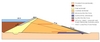
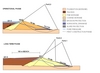
A horizontal drainage is placed under the downstream part of the embankment to help keep the pore pressure low during the operational phase and increase the leakage control (Figure 3).
The moraine used as the main dam fill material is divided into two different material types, coarser moraine placed downstream and finer moraine placed upstream in the cross section. The purpose of this distinction is to increase the drainage of the downstream part of the embankment thus lowering the pore pressure and increasing the stability. Note that the difference in gradation and hydraulic conductivity between the fine and coarse moraine is small and has no definitive boundary. A massive material testing program during the first construction phase showed that the conductivity of the coarse moraine varies between 10-7–10-6m/sec and the finer moraine between 10-8–10-7m/sec.
Dimensioning criteria
Stability and pore pressure calculations have been performed in the geostudio software environment – Seep/W and Slope/W.
Several calculations describing stability and pore pressure during operational and the long-term phase have been carried out.
In the operational phase calculations, the horizontal drainage has been assumed to be properly functioning and the differentiation of finer and coarser moraine is assumed to be adequate, i.e. satisfying difference in hydraulic conductivity has been achieved. The angle of friction of the moraine has been set to 35°.
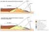
Stability calculations of the operational phase with the assumptions mentioned above renders a factor of safety of approximately 2 for both shallow slip surfaces and for deeper slip surfaces. This indicates that no stability issues are expected during the operational phase (Figure 4).
During the operational phase, a beach will be constructed forcing the free water surface away from the embankment, thus minimising the risk of wave erosion and lowering the pore pressure through the embankment. The beach will have a conventional dry cover in the long term phase.
Stability calculations of the long term phase, describing a fully functional embankment with a properly designed beach have also been carried out. The calculations verify that the stability is adequate in this case, with factors of safety of about 2 (Figure 4).
A major criteria in calculations of long-term stability has been that the embankment must be stable even if the horizontal drainage has deteriorated. This criteria is set due to the likeliness of a gradually failing drainage effect caused by slow material transport, chemical or biological processes during the long term phase.
In combination with this criterion the phreatic surface has then been calculated for two different cases.
• The differentiation of finer and coarser moraine during the construction is adequate, i.e. satisfying difference in hydraulic conductivity has been achieved and will remain.
• The differentiation of finer and coarser moraine is not achieved with regards to hydraulic conductivity and the embankment is regarded as homogeneous when calculating the phreatic surface.
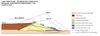
Stability calculations with the assumptions mentioned above renders factors of safety of approximately 1.7-2.0 for both shallow and deeper slip surfaces. This indicates that no stability issues are expected during the long-term phase (Figure 5).
These results can be expected by comparison with natural formations. Slopes of moraine have naturally come to a slope of about 1V to 3H since the last ice age.
Sweden is situated in a geologically stable environment where the common approach is not to consider earthquake induced loads in embankment design, i.e. the seismic loads are considered to be lower than allowable increase in stresses under extreme loads. However due to the shear length of time these embankments are expected to last, the occurrence of considerable earthquakes might still need to be taken into account even in a geological stable area like this. During an earthquake of high magnitude there is an imminent risk of liquefaction of tailings inside the reservoir. It is therefore necessary to ensure that the construction is stable even during this type of extreme load. Control calculations have been executed with the assumption of full liquefaction in the tailings. The result of the calculations implies that the slip surfaces influenced by the liquefied tailings has a factor of safety well over what’s required in such an extreme event (Figure 6).
Monitoring
The main focus of the monitoring program is to measure seepage through the embankments and their foundation, phreatic surface and displacements of the crest.
Displacements are to be measured manually on concrete plinths installed in wells on the dam crest. The plinths have to be founded deep enough to ensure that measurements are not disturbed by freeze and thaw actions since frost can reach some 3m into the ground during winter.
The phreatic surface is, in a number of cross sections, measured by means of stand pipe piezometers. In each cross section a number of pipes are installed at different distances from the crest. In some of the locations pipes are installed with filter tips at different depths of the embankment and foundation. This is to ensure a correct measurement even if the pore pressure is not hydrostatic.
Seepage is collected in a pipeline placed under the downstream toe of the embankments. Measuring the amount of seepage will be done continuously in a number of measuring wells along the embankments. The distance between measuring points is between 100 and 300m.
Piezometers and seepage measurement can only be done in specified cross sections and there will always be a distance between measuring points where conditions have to be assumed to be similar to what is being observed. A possibility to indirectly observe conditions continuously along embankments has arisen in recent years by means of temperature measurements. By using fibre optic cables and a special laser instrument, temperature can be measured with an accuracy of less than 0.1 degree and 1m along the cable.
These types of temperature measurements will be used in the actual embankments and can be described as a passive system based on natural variation of temperature in the reservoir. In summer time the temperature in the reservoir will be some 15 to 20 degrees centigrade and in winter close to zero. The temperature below the phreatic surface within the embankment will follow the seasonal variation like a sinus wave with an amplitude and phase that depends mainly on a few parameters such as length of flow path and permeability of materials.
The maximum temperature deep inside an embankment will normally be observed several months after the peak temperature of the reservoir. However if there is a zone with higher seepage than average this will be noted both as a higher amplitude and that the peak comes sooner.
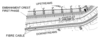
In parts of an embankment above the phreatic surface (but still far enough from the ground surface) the temperature variation is much smaller than below. This can be used to detect the position of the phreatic surface by placing a fibre optic cable in such a way that the expected phreatic surface is crossed as many times as desired. Figure 7 shows a plan of the chosen placing with one fibre placed in a square pattern 20 by 20m. In this way the phreatic surface can be observed every 20m as long as it is positioned within plus or minus 10m from what is expected. The fibre optic cable is also marked on the cross section shown in Figure 2.
Construction phase
Figure 8 shows a picture of the ongoing construction. The embankments are to be built in two stages. The first construction stage started in 2008 and will be completed during 2010. The second stage is planed to be built in approximately 10 years.
In the first stage the embankments are being built up to an elevation of 219m above sea level, with a maximum height of about 16m. In the second construction stage the embankments will be raised an additional 5.5m reaching up to an elevation of 224.5m above sea level.
The first construction stage has been designed with the second stage in consideration, e.g. the foundation of stage two has already been prepared in the first construction stage.
The total crest length of the embankments is 3600m and the fill volume is 2Mm3. Of this about 1.2Mm3 is filled in stage 1.
Rehabilitation and control phase
During the first 30 years after closure the behaviour of the embankments will be monitored. Regular evaluations will be performed to ensure that the design fulfils requirements for long-term stability.
For more details contact: Sweco Infrastructure AB, Gjörwellsgatan 22, P.O. Box 34044, SE-100 26 Stockholm, Sweden. Tel: +46 8 695 60 00. www.sweco.se