Pumped storage
Handling rejection
9 September 2004Wei-yun Shao analyses the general characteristics of casing pressure under abnormal turbine load-rejection conditions by employing the method of characteristics for transient flow
Pumped storage power plants have a number of essential features, including the fact that they can not only operate independently in several modes, such as generating, spin-generating, pumping, spin-pump and standstill, but can also change operating states from one to another quickly to meet the needs of a wide range of system operations .However, the mode changes may cause overpressure under extreme conditions due to the overspeed effect. The maximum pressure on the spiral casing inlet section caused by a turbine full-load rejection is the key factor to guarantee the safety of hydraulic conveyance structures, as well as the whole pumped storage plants. One example of failure due to the overpressure is the failure of Dartmouth turbine casing in May 1990(Price,1998).
After the foundation of waterhammer theory, the method of characteristics was developed rapidly as the standard technique for transient analysis in the 1970’s (Swaffield and Boldy, 1993). Since then, a great deal effort has been devoted to evaluating the maximum overpressure occurring in the water conveyance system (Liu and Chang, 1999; Ramos and Almeida, 2001; Kameswara and Eswaran, 1999), and testing (You, 2000). However, there has been little research concerned with the characteristics of transient pressures in the penstock and in the spiral casing. In this paper, the transient theory is used to analyse the characteristics of pressure at the turbine casing inlet section (casing pressure).
Theoretic analysis
In pumped storage plants, the two-segment closing law is commonly adopted as the closure law at turbine load-rejection. Two types are most commonly used. The first is F-S closure law which closes turbine guide vanes fast then slower. The second is S-F closure law which closes slowly first then fast (see Figure 1). The intersection of two segments (line MB and BN) is the changeover point B, whose corresponding opening and time are yb and tb respectively. In this paper, all turbine load rejection operations are following F-S closure law.
In this paper, the method of characteristics (Wylie and Streeter,1993) is used to analyse the casing pressure rise at time t and the pressure at i-1 section at time

C+:

(1)

(2)
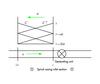
where subscript t denotes instantaneous quantities at time t, subscript i indicates the parameters at the casing inlet section(see Figure 2).
Combining Equation (1) and Equation (2), the casing pressure at time t can be expressed as

(3)
Generally speaking, Q is at the order about 101~102, R is about 10-6~10-9 and B is 105~108 times greater than R. As a consequence, the fourth term in Equation (3) can be neglected and the equation reduces to

(4)

(5)
where

The casing pressure will rise only when

When the turbine load is tripped, the pressure surge wave propagates upstream. Consequently, the variation of parameters at i-1 section have a time delay than those at spiral casing inlet section (i section) (see Figure 2), namely

Hence we can assume

with a coefficient k1 which is greater than 1.0. The last term in the right side of Equation (5) can be rewritten as

(6)
Substituting Equation (6) into Equation (5) results in

(7)
Where

For turbine load rejection, the discharge at last time step

is always greater than that at the same section at present time t, Qi,t, so we have

Similarly

Pressure peak corresponding to the changeover point B of closure law
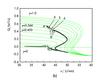
When the turbine load is tripped, guide vanes are kept closed following the F-S closure law as shown in Figure 3a. As a result, the speed of the unit is increased, the discharge is decreased and the unit begins to move away from the turbine normal operating zone towards the S-shape zone (along A’B’ or A’B’(2) in Figure 3b). In the limited range where A’B’ passes through, the slope of the discharge characteristics curve becomes gradually bigger. The discharge decrement at the present time

must be greater than that at the previous time step

Based on Equation (7), the pressure at time t, Hi,t, is greater than that at time

the casing pressure rises. Because the unchanged closing rate of AB, the condition of

will be maintained until point B’ is reached Consequently, the casing pressure rises continuously (A”B” in Figure 3a).
Once the opening of the turbine gate is closed to the corresponding opening yb of changeover point B of closure law, there exist two different cases: point B’ is located outside the S-shape effect zone and point B’(2) is inside (in Fig.3.b).
The zone related to A’B’ is outside the S-shape effect zone, therefore the discharge strongly depends on 
instead of the variation of unit speed. If the two slopes of AB and BC of the F-S closure law are significantly different, the sudden slow down of the guide vane closing will induce the sudden decrease of the magnitude of
at time tb. As a result, the decrement of discharge 
at time 
is less than 
at time 
Based on Equation (7), Hi,t is less than which means the casing pressure drops suddenly. In other words, the pressure reaches its first pressure peak (point B” in Figure 3a) at the moment when the guide vane opening is closed to the opening yb. This trend of pressure drop will be maintained (B”D”) until the unit enters into the S-shape effect zone. However, if the two segment slopes of the F-S closure law are nearly equal, the difference between 
and 
is small, there is no obvious pressure peak corresponding to the changeover point B (case of 3 in Fig.4.a).
With regards to A’B’(2) the point B’(2) is located inside the S-shape effect zone. The variation of unit discharge after point B’(2) is strongly dependent on the variation of unit speed 
while 
has a much smaller effect on it. Consequently, there is no obvious pressure peak appearing corresponding to the changeover point B of closure law (case of 3 in Figure 4a).
Maximum pressure peak
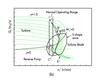
Almost all reversible pump turbines have the S-shape effect zone covering turbine brake zone and reverse pump zone. The unit can enter into the turbine brake zone and reverse pump zone due to the large rotational mass inertia of the pump turbine. It is a S-shape effect zone in which discharge varies rapidly with the variation of the unit speed. After D”, 
occurs due to the rapid decrease of the discharge. The casing pressure turns into an increase (D”C” ) until it reaches the point C”, which is a point corresponding to the minimal unit speed in reverse pump mode on transient discharge curve . After C’, the decrease of discharge (see C’E’) becomes gradually slower than that (see B’C’) before C’ 
occurs around point C’, and casing pressure drops just after C’ based on Equation (7). Therefore, the case pressure achieves its maximum at point C” ( Figure 3a).
Case study and discussion
Table 1 lists a series of cases of turbine load rejection in two pumped storage plants. Their nominal head and maximal static head are 526m, 610.2m and 224m, 286.2m respectively. They can be extended as the typical representation to cover most high head pumped storage plants and the mediums.
In table 1, all parameters are the same in each group except the time tb related to the opening yb,.
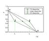
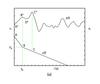
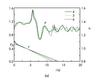
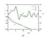
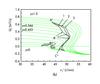
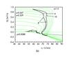
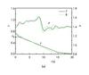
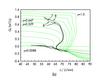
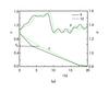
Figures 4 to 7 illustrate the casing pressure, p, and the opening of guide vane, y, in function of the time, and the unit discharge,
in function of the unit speed,
When F-S closure law is applied at turbine load rejection and point B’ is away from the S-shape effect zone, the casing pressure has two pressure peaks regardless of the nominal head of pumped storage plant (see cases of 1,2,4,5,6,7,9 as shown in Figure 4~Figure 7).
The first pressure peak occurs at the point B’ and the second corresponds to the first minimal unit speed on transient discharge curve in the reverse pump mode, .
On the other hand, the figures show that the maximum pressure peak in the medium head pumped storage plants is not as obvious as those in high head plants (comparing cases of 1,4,7 and 9). Most of those casing pressures in the medium plants usually keep pulsating once the units get into the S-shape effect zone, such as in the case of 7,8,9 and 10.
Once point B’ is located inside the S-shape effect zone, the pressure peak corresponding to the changeover point B disappears due to the rapid variation of the discharge in this zone, such as case 3 in Figure 4.
Summary
Generally speaking, when the turbine load is tripped, the casing pressure has two pressure peaks if the F-S closure law with two significantly different slopes is applied, and the point is away from the S-shape effect zone. However, if the difference between the two slopes is small, the first pressure peak will not be obvious. On the other hand, if the point is located inside the S-shape effect zone, the pressure peak corresponding to the changeover point B will be unobvious.
In practical engineering, the closure law is one of the most important parameters to keep the overpressure away from the water conveyance system. The characteristics of the casing pressure at turbine load rejection in pumped storage plants are much different if the different closure laws of guide vanes are applied.
NOMENCLATURE

Time-step size 
Dimensionless opening decrement at each time step
Pipeline characteristic impedance

Instantaneous piezometric head
proportional parameters
unit speed of pump turbine
dimensionless casing pressure
instantaneous discharge at a section
unit discharge of pump turbine
pipeline resistance coefficient
corresponding time at changeover point B of the closing law
dimensionless guide vane opening
dimensionless opening at changeover point B of the closing law
Capital letters in figures: A,A’,A” correspond to the start point of the action of turbine load rejection; B,B’,B” relate to the changeover point B of the closure law; C,C’,C” indicate the point whose unit speed is minimum on the transient discharge curve in the reverse pump zone
TablesTable 1