Installing the Turbinator
22 December 2010CleanPower has installed its first Turbinator at the Hegset dam in Norway. The Turbinator combines an axial turbine and generator in a compact and sealed machine, and can utilise lost hydropower potential from environmental outlets
The long term political context for hydropower in Europe is at the same time challenging and interesting. The overall goal of the Renewables Directive (2009) is that 20% of total European energy consumption shall come from renewable sources by 2020. At the same time the Water Framework Directive of 2000 (WFD) aims to improve the aquatic quality of all water bodies, including riverbeds downstream of hydropower dams, by 2015.
In order to preserve aquatic flora and fauna, many hydropower dams are obliged to release a certain amount of water for all or parts of the year. This release is called the reserved environmental flow, and the implementation of the WFD will give a substantial increase in such flows. As one example edf, the largest French hydropower producer, has estimated the consequences of implementing the WFD is equivalent to shutting down an 800MW power plant.
CleanPower AS based in Kristiansund, Norway has developed a combined axial turbine and generator called the Turbinator. This is particularly well-suited for producing hydropower from environmental outlets. Besides being optimised for the right flow/head window, it is compact, has a fully sealed generator cooled by the water flow, and accommodates a simple installation site not even needing a power house. A pilot installation was completed in 2010 in cooperation with European renewable energy producer Statkraft AS.
Technical description
The Turbinator is a low head axial turbine where the turbine and generator are integrated, making a compact unit with small footprint. The turbine has a fixed pitch runner and the pilot model has a variable pitch guide vane assumed to become fixed in the final version. The generator is a permanent magnet synchronous machine, fully designed by CleanPower. The rotor of the generator with permanent magnets is fixed directly to the outside of the turbine runner (tip driven), meaning the entire generator / turbine assembly has one single rotating piece. On the upstream side, the Turbinator has a simple bolted flange connection to the pipe, and a suction pipe downstream completes the water way.
The control system features fully autonomous operation under remote surveillance and is adaptable to customer requirements which could in future include complex algorithms for optimized production.
Development
The turbine was designed by Evald Holmén of Sweden. He has designed turbines for half a century, and is an internationally renowned expert on hydropower turbines. The design is based on a Kaplan turbine he has previously worked with, by transforming the waterway in front of the runner to the required tubular shape. Model tests on that Kaplan turbine showed a peak efficiency of 92.2 %. The model turbine was a normal Kaplan design with a spiral casing and guide vanes. Its eight-blade design gave a margin in cavitation resistance. A relatively big hub diameter on the model turbine eliminated a part of the difference in runner inlet velocity as function of the radius between Kaplan and tubular turbines.
The model test data estimated that for the required performance, a runner diameter of 660mm and a blade angle of 19 degrees was required. In the simple tubular design it was contemplated to have guide vanes in a fixed position, but the transformation of the guide vanes from an axial ring to a radial ring made it difficult to estimate the optimum cam angle for the guide vanes. In this pilot model a movable guide vane ring having 18 vanes was therefore installed. From measurements of the pilot model at different heads a calibration of the on cam angle can be made for use in future applications of the Turbinator – with the intention of having fixed guide vanes to simplify and increase the robust nature of the construction.
Test runs after installation show expected performance data regarding power output. Constraints in the installation makes it difficult to accurately measure the absolute discharge, but relatively big pressure losses in the pipe (dia. 450mm) through the dam body makes it possible to measure relative discharge and to find the relative efficiency. It is always the runner that determines the discharge through the turbine in a certain operating point at peak efficiency, so the model test discharge 1.2m3/sec was used for calibrating the relative discharge.
The generator is designed by Øystein Krøvel of CleanPower AS. It is an eight-pole permanent magnetised synchronous generator with surface mounted magnets. The stator features classic integer distributed winding with random round wire coils. A special feature of the generator is the wet air gap, requiring waterproofing of both the magnets and the stator, resulting in a large distance between rotor and stator. The permanent magnetised rotor is advantageous compared with induction and field wound synchronous generators with a large wet air gap.
The generator is connected directly to the grid without the converter commonly used between permanent magnetised machines and the grid. Being permanently magnetised, the generator cannot regulate the voltage and/or the reactive power. The reactive power flow is thus dependent on the grid parameters, ie the voltage at the terminals. The design has to take into account the different operating points choosing a suitable voltage drop to make sure the generator can operate within the expected range. The chosen grid transformer has steps, enabling adjustment for larger seasonal changes or more permanent changes on the grid.
As the generator and turbine designs must match, this implies some restraints such as turbine speed (maximum rpm and synchronous speeds) and diameter. The inner diameter of the rotor is the outer diameter of the runner. This gives a much larger rotor diameter than what would normally have been chosen for the specified speed and power rating, resulting in a short machine with a ratio between the active length and air gap diameter of one-third. The rotor and stator yokes are kept as thin as possible to minimise the outer diameter of the machine. The thin yokes are heavily loaded magnetically (to avoid too high magnetic losses) but still keep the generator slim. It has been chosen to reduce the magnetic loading by increasing the stator length somewhat. The successful integration of the generator has given a slim and compact machine with a very good overall performance, says CleanPower.
Advantages
The design of the Turbinator has been focused on achieving a simple and robust construction where a governing design trade-off has been to favour simplicity over peak efficiency. By this approach the Turbinator has the potential of opening up for hydropower installations in sites previously not financially viable. Its main features are:
• Simple and robust design with only one rotating part.
• Small footprint for cramped installation sites.
• Simple installation to a pipe flange.
• Limited civil works – a simple concrete foundation to ensure stability.
• Sealed generator efficiently cooled by the water stream.
• Can stand outdoors – a protective building is not needed.
• Good efficiency.
• Low noise.
Ease of installation
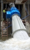
Compared with a traditional small hydropower installation, the Turbinator demands only very basic preparations and civil works. It is connected upstream to a pipe flange with a motorised valve that is governed by the control system. Bolting it to a concrete slab ensures stability. A downstream suction pipe ensures a continuous water string all the way to the downstream water level.
The control system is installed in an existing building near the Turbinator. To enable remote control via internet, this location needs an internet line (can be wireless via GSM/GPRS or similar). Signal cables are run between the control system and Turbinator, and power cables from the Turbinator to the grid transformer via the control system.
In a traditional small hydropower installation, the non-electromechanical parts are usually around 70% of the total investment. Due to the simplified installation, non-electromechanical costs are expected to be less than 50% of the total investment for a Turbinator plant.
Pilot installation at Hegset dam
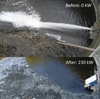
The first full scale demonstration model was piloted at the Hegset dam in August 2010. Located on the Nea river in Sør-Trøndelag county, Norway, the dam has an environmental outlet obligation of 1.5m3/sec during five summer months, with the measurement point situated 6km downstream. The environmental outlet pipe through the dam is slightly under dimensioned, providing an estimated 1.2m3/sec from the dam, but water from adjoining creeks adds up to ensure the required minimum flow at the measurement point. The Nea river is known for good trout fishing, so all necessary precautions must be taken to preserve the aquatic environment.
As a known limitation for the project, the 450mm pipe through the dam gives an estimated 4m pressure loss, around 15% of the gross head. The gross tidal range is 24.6-30.6m.
As this is a new design with unproven characteristics, the pilot installation was awarded public co-funding through Innovasjon Norge (the state-owned company in charge of such funding in Norway). The total project cost was around €690,000 (US$) including extensive development and engineering activities, and a non-optimised supply chain including a custom-built generator.
The Turbinator pilot model installed was completed on 14 October 2010. It had been operational more than 98% of the time. Most of the down-time was after automatic shut-downs due to nightly power outages. The pilot plant has during 1500 running hours in 2010 delivered 0.35GWh (average of 234kW). The Turbinator has been disassembled and inspected. It will be stored for the winter before being installed again in April, ready for the start of the next season on 1 May 2010.
Further development
Looking to the future, the primary objective for the Turbinator is to industrialise the design. All necessary adjustments to minimise manufacturing costs need to be carried out. This includes defining physical standard sizes within which the runner and generator will be adapted to fit the data for each installation site. For some sites adding a frequency converter would increase the system flexibility. It would enable voltage and reactive power regulation, and also enable runner speed adjustments that would in turn adjust optimum operating point and water flow as a function of head. The advantages of adding a frequency regulator must be balanced against added cost and power losses.
Optimum configurations for non-grid operation (eg autonomous powering of a rural village) will be studied, as well as advanced bearing systems, which could be permanent magnet or water cooled composite based bearing systems.
The authors are Egil Opsahl, Managing Director CleanPower AS, Kristiansund, Norway, Evald Holmén, Evald Holmén Consulting, Stockholm, Sweden, and Øystein Krøvel, Tech Manager, CleanPower AS, Kristiansund, Norway. www.cleanpower.no
| Who's who? |
| The companies involved in the Turbinator pilot project were: |
| Pilot installation at Hegset Dam |
| Location: Hegset dam, Tydal, Norway |