Investigating Val Noci
29 November 2010Mattia Pinotti and Adriano Lais give an indepth look at physical model investigations which were carried out on the morning glory spillway at Val Noci dam in Italy
Mediterranea delle Acque (MdA) operates the Val Noci reservoir in Italy as a drinking water supply. A recent estimation of the flood hydrograph has shown that the peak discharge exceeds the existing discharge capacity of the three spillway structures. An additional morning glory spillway was therefore planned to increase the hydraulic capacity. The Laboratory of Hydraulics, Hydrology and Glaciology (VAW) of ETH Zurich, Switzerland, was commissioned to investigate the design of the new spillway in a physical model with a scale factor of 25.
The model tests of the initial design showed that mean minimum pressures may drop below vapour pressure during the transition from free to pressurised flow condition in the vertical shaft, resulting in a phase change from water to vapor. As this may cause structural damage due to strong vibrations as well as limited spillway capacity in the prototype, VAW optimised the design by widening the vertical shaft and installing a throttle at the end of the bottom bend. Furthermore, overflow piers were added to the morning glory crest to ensure radial inflow conditions and avoiding air-entraining vortex formation. The required discharge capacity of 75m3/sec is ensured and extreme pressure fluctuations are limited. However, in the upper section of the vertical shaft, sub-pressures may locally drop below vapor pressure during the transition phase from free to submerged inflow.
Project overview
Water is stored by a 56m high masonry gravity-arch dam with crest elevation at 540.5masl, harnessing the valley of the Noci River with a catchment basin of 7.6km2 and creating 3.4Mm3 of live storage (figure 1). The dam project dates back to 1922. Excavations began in 1923 and the construction works for the dam ran from 1925 to 1931.
Three spillway structures (gated chute spillway, middle and bottom outlet) with a total spilling capacity of 240m3/sec at the maximum expected flood level (MFL) of 538.97m asl were used for flood evacuation prior to the design flood update (figure 2). The chute spillway is located at the right abutment and is equipped with a radial gate of 10m wide and 4m high. The discharge capacity of the fully opened chute spillway totals 190m3/sec at MFL. The middle outlet consists of a bell-shaped valve (Verrina valve) with a capacity of 34m3/sec at MFL, conveying the water through the former diversion tunnel. The bottom outlet with a discharge capacity of 16m3/sec at MFL consists of a fibreglass cased steel pipe with an inner diameter of 1m, operated by a cone valve situated at 491m asl.
A new estimation of the design flood hydrograph performed by the Italian National Hydrographic Service in 2003 assessed a maximum inflow into the reservoir of 280m3/sec and a total flood volume of about 3.8Mm3 for an event with a return period of 1000 years. Because this discharge exceeds the existing total spilling capacity, MdA planned to erect an additional morning glory spillway. The concept aimed at increasing the spillway capacity using a reliable spillway structure which operates automatically and requires minimum maintenance while minimizing impact on the existing structures.
The new morning glory spillway is located at the right valley flank, close to the gated chute spillway, and uses the existing middle outlet tunnel for a time and cost saving design. The project includes a new stilling basin to ensure adequate energy dissipation at the tunnel outlet.
The routing of the design flood hydrograph through the reservoir with the chute spillway, the bottom outlet and the morning glory spillway in operation (the middle outlet is not considered), predicts a peak rate of 75m3/sec released through the morning glory spillway at a reservoir water level of 538.9m asl (design discharge).
The Laboratory of Hydraulics, Hydrology and Glaciology (VAW) of ETH Zurich, Switzerland, was commissioned to investigate the designed morning glory spillway. The physical model tests aimed at evaluating the discharge capacity, the approach flow conditions and the flow conditions in the vertical shaft in order to test the overall hydraulic behaviour of the new structure and to improve its operating efficiency and safety. The investigation also included tests on the modified middle outlet tunnel and the new stilling basin. The model construction was completed at the end of 2006, the investigations on the morning glory spillway in the middle of 2007.
Hydraulic scale model
A prototype reservoir area of about 10,000m2, a portion of the right valley flank and the spillway structures of the Val Noci dam were reproduced in a 1:25 physical scale model using Froude similitude (see figure 3). Although this similitude guarantees adequate reproduction of the prototype conditions in the model, accurate modelling of all hydraulic parameters with the same hydraulic model is impossible. For example, scale effects related to the water viscosity and surface tension are significant on the discharge capacity at small overflow depths. In the present experiments scale effects are negligible for prototype overflow depths higher than 0.55m, ie for morning glory discharges exceeding 22m3/sec.
Initial design
Layout
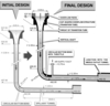
The initial design of the morning glory spillway consisted of the following (see figure 4):
• i) A cup-shaped overflow structure (transition tube) with a crest elevation at 537.5m asl, and a crest diameter of 8m, designed for an overflow head of 1.2m and approximately representing a Creager profile.
• ii) A 32.04m high vertical shaft, 2m in diameter, connected to the overflow structure at 530m asl (throat of the transition tube).
• iii) A circular bottom bend with a radius of curvature of 4m.
• iv) A 26.84m long spillway tunnel, 2m in diameter and with a slope of 1.6%, joining the existing middle outlet tunnel at an elevation of 492.52m asl. The initial design did not include any aeration device.
Discharge capacity
For reservoir levels up to 538.75masl, the flow is governed by the crest discharge characteristics, ie the discharge over the morning glory overflow structure can be expressed as
where Cd is the discharge coefficient, R=4m the crest radius and H denotes the overflow head. According to the service regulation, the chute spillway is fully opened for reservoir levels above 538.2m asl. At this water level the chute spillway discharges 150m3/sec.
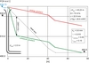
For this case, a strong current towards the chute spillway influences the approach flow to the morning glory spillway, resulting in a slightly decreased discharge capacity and a diminished value of Cd=0.468, compared to the hypothetical scenario with the chute spillway out of operation (figure 5). The value of Cd=0.468 results from interpolation of measured data. For reservoir levels above 538.75m asl the overflow crest is submerged and the entire morning glory spillway operates under pressure. Therefore, the flow control section changes from the crest to the downstream end of the spillway tunnel. During a pressurised flow regime even a considerable increase of the reservoir water level leads to only an insignificant gain in spilling capacity.
Flow conditions and pressures in the vertical shaft
Annular flow in the overflow structure occurs up to a discharge of approximately 40m3/sec. The overflow nappe clings to the invert of the cup-shaped overflow structure and a free air core remains in the centre of the vertical shaft. As the discharge increases, the overflowing annular nappe becomes thicker and converges into a solid vertical jet at the crotch point. The air-water flow chokes the vertical shaft and free air entrainment is prevented.
The flow regime changes from free to pressurised flow conditions and a so-called ‘boil’ forms above the crotch point. Both the boil and the crotch rise progressively higher for increasing discharge. Due to the high available net head and the absence of free surface aeration, sub-atmospheric pressures are measured at the throat of the transition tube. Due to the lack of a throttle in the hydraulic system, the vertical shaft is exposed to negative pressures close to the vapour pressure for discharges of approximately 50m3/sec.
At higher discharges, up-scaled pressures at the throat of the transition tube drop below vapour pressure resulting in a phase change from water to vapour, ie the water column separates. Therefore, the flow is governed by this section and the available net head is strongly reduced, resulting in a restricted discharge capacity.
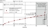
For a theoretical net head of 45.23m between the reservoir water level (538.73m asl) and the tunnel axis elevation just upstream of the junction with the middle outlet tunnel (493.5m asl), a calculated discharge of 72m3/sec results from the Bernoulli equation. The corresponding energy and pressure gradients are shown in figure 6. The calculated relative minimum pressure of –19.4mWC (meter water column) at the throat of the transition tube agrees well with the measured and up-scaled value of –19.5mWC.
The phenomenon of water column separation could not be reproduced in the hydraulic model, as Froude similarity would theoretically require a reduction of the atmospheric pressure in the model. The maximum prototype discharge of the initial design of the morning glory spillway has been calculated theoretically. If it is assumed that the pressure at the throat of the transition tube is equal to vapour pressure and full pipe flow conditions occurring in the vertical shaft, a discharge of 58m3/sec results. For this discharge, the water column would separate, ie the discharge capacity of the initial design of the morning glory spillway is limited to some 58m3/sec.
Optimisation and final design
The initial design modification aimed at improving the flow conditions in order to ensure safe operation, avoiding water column separation at the throat of the transition tube. The modification should also increase the discharge capacity to 75m3/sec. VAW developed a modified design consisting of:
• An increase of the shaft diameter from 2-2.35m resulting in a crest diameter of 8.35m, without altering the drop inlet location and shape.
• A re-design of the bottom bend, including a throttle at its end, to raise the pressure gradient ensuring pressures higher than the maximum tolerable negative pressure head of –(7 to 8)mWC at the throat of the transition tube. According to common design criteria, this is the minimum pressure head to avoid water column separation.
• An increase of the spillway tunnel diameter to 2.35m.
• The addition of an air supply duct of at least 0.7m in diameter behind the bottom bend to ensure sufficient air supply and free surface flow in the spillway tunnel.
Approach flow conditions
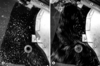
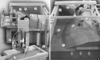
The approach flow towards the morning glory is influenced by the protruding slope of the right valley flank and the service building foundation nearby. However, for small discharges, all-around radial flow occurs in the vicinity of the morning glory crest (see figure 7a). At higher discharges the main flow towards the open chute spillway circulates around the morning glory (figure 7b). Therefore, a strong current develops in the region between the morning glory overflow structure and the right valley flank.
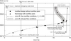
This flow is deflected by the service building foundation, which negatively influences the velocity distribution in the vicinity of the morning glory. For reservoir water levels higher than 538.9masl, a bathtub vortex develops in the morning glory overflow structure. A considerable amount of kinetic energy is stored in the strong rotational motion resulting in a reduction of the discharge capacity, ie the discharge decreases for increasing reservoir water level (figure 8). With increasing reservoir water level, the vortex persists and the discharge capacity is diminished.
The maximum discharge transported by the modified design of the morning glory spillway reaches 72m3/sec at 538.9masl. Consequently, the modified design did not reach the required discharge capacity of 75m3/sec.
For the final design, four overflow piers (0.4m wide and 2m long) are implemented on the modified design of the morning glory crest ensuring radial inflow conditions (see figures 4 and 9).
The design discharge of 75m3/sec is attained at a water level of 538.8masl. The flow condition has then just turned from free to submerged at the morning glory overflow structure. The overflow piers enforce radial inflow and suppress the vortex formation enhancing the hydraulic performance. However, the current along the right valley flank towards the open chute spillway is still strongly deflected by the service building foundation. A three-dimensional flow field develops resulting in a single vortex-jet in the vicinity of the morning glory crest. This vortex may lead to erosion processes in the surrounding area and debris entrainment.
For discharges higher than 75m3/sec and for reservoir levels above 538.8masl, the morning glory spillway operates under pressure. The vertical shaft, however, already chokes for discharges superior to 56m3/sec. For the maximum emergency water level of 538.97masl, a discharge of 76.7m3/sec was measured.
Dynamic pressures
For discharges up to 40m3/sec the mean pressure heads, along the cup-shaped overflow structure and the vertical shaft, are near the atmospheric pressure and the pressure fluctuations are rather small. For discharges higher than 56m3/sec, full pipe flow conditions are observed and sub-atmospheric pressures occur in the upper part of the vertical shaft. A minimum mean value of –6.53mWC is detected at the throat of the transition tube for a discharge of 75m3/sec (final design with overflow piers). This is in accordance with the design criteria. Nevertheless, up-scaled local sub-pressures drop below vapour pressure. These low pressures lead to flow pulsations with considerable pressure peaks, probably including the formation of localized cavitation bubbles. These phenomena may damage the concrete surface. As a certain amount of air is entrained into the flow, the negative consequences are minimised.
Prototype experience with similar structures shows no cavitation damages if the mean pressure is above the vapour pressure. The occurrence of extreme minimum pressures below vapour pressure could be avoided by raising the pressure gradient in order to obtain a higher mean pressure at the throat of the transition tube. This may be achieved by vertical shaft enlargement and adequate throttle orifice adaptation.
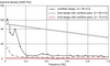
Particular attention has to be paid to the pressure fluctuations in the vertical shaft due to the formation of an oscillating boil and two-phase flow phenomena during the transition phase from free to full pipe flow. These pressure fluctuations are analysed by determining the spectral density of a time series, ie the frequency of the measured pressures. For a discharge of 65m3/sec the spectral density shows one distinct peak at 0.03Hz (figure 10). This is the well-defined oscillation frequency of the boil causing a pressure amplitude of 1.8mWC for the modified design and 0.7mWC for the final design with overflow piers.
During submerged inflow conditions, ie for Q= 75m3/sec, the asymmetrical approach flow conditions towards the morning glory spillway without overflow piers, lead to the formation of an air-core vortex within the overflow structure. This phenomenon causes additional intensive pressure fluctuations due to unstable flow conditions as the air core bathtub vortex intermittently collapses in the inlet structure (figure 11). Instantaneous fluctuations up to 20mWC are detected. The final design with overflow piers avoids this bathtub vortex formation, reducing the pressure fluctuations. The spectral analysis shows no peaks, ie no significant pressure fluctuations occur in the vertical shaft.
Construction works and operation
The update of the total available spilling capacity of the Val Noci reservoir is a part of a major maintenance plan which includes works at the dam and all its auxiliary structures.
The construction works for the morning glory spillway started in 2008. The vertical shaft was carried out by raise boring after rock mass concrete reinforcements at construction site. The overflow structure’s internal profile was obtained using a prefabricated steel formwork. To date, no significant information about the morning glory operation is available.
Mattia PINOTTI, Dipl. Bau-Ing. ETH, Hydraulic Engineer at Lombardi Engineering Ltd., Minusio (Switzerland), formerly: Laboratory of Hydraulics, Hydrology and Glaciology (VAW) of ETH Zurich (Switzerland), Email: mattia.pinotti@lombardi.ch
Adriano LAIS, Dipl. Bau-Ing. ETH, Head of the Hydraulic Structures Division at Laboratory of Hydraulics, Hydrology and Glaciology (VAW) of ETH Zurich (Switzerland). Email: lais@vaw.baug.ethz.ch