PUMPED STORAGE
KANNAGAWA
Out of sight
24 June 2004Kenji Aoki digs under the surface of the Kannagawa hydroelectric plant, the latest in a series of pumped storage facilities built in Japan by TEPCO
UNDERGROUND spaces in Japanese rock masses are mainly used for building energy-related facilities.
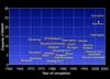
The full-scale use of underground spaces has been closely related to the energy policy of the Japanese government since the second world war. In the late 1950s, energy demand started to increase rapidly along with a steady restoration of the country’s economy. Since the late 1960s, when the demand for electricity rapidly grew and the output from nuclear power generation steadily increased, the construction of large-scale underground pumped storage power plants started to cover temporary power shortages during peak loads. These power plant caverns are the most important and marked examples of rock engineering and the use of rock caverns.
Around 50 underground power generation plants have been constructed in Japan to date, including almost 20 hydraulic plants and about 30 underground pumped storage power plants. Many large-scale hydraulic projects have been constructed underground, enabling large pressure heads to be formed and high capacity plants to be built at lower costs.
The first underground hydraulic power generation facility in Japan was Hokkaido’s Uryu power plant completed in 1943. The first underground pumped storage power plant was the Shiroyama power plant completed in 1965. Since the construction of the Shin Takase-gawa power plant which started in 1971, various plants – with large cavern volumes of 200,000–300,000m3 – have been constructed by solving various technological difficulties like high earth pressure and highly fractured rocks.
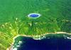
Recently, the Kazunogawa and Kannagawa pumped storage plants have been completed. A test pumped storage power plant using seawater has been completed in Okinawa and started to operate in 1998. A variation of the underground pumped storage power plant is also being planned, with the power house and the lower reservoir underground to obtain a large pressure head. The feasibility of other new types of power storage facility is also being investigated.
Kannagawa hydroelectric plant
The Kannagawa hydroelectric plant is a pumped storage power scheme, currently being constructed by Tokyo Electric Power Co., Ltd (TEPCO). It bestrides the Tonegawa river in Gunma prefecture and Shinanogawa river in Nagano prefecture. With a maximum output of 2800MW, it is to be one of the largest pumped hydro power projects in the world.
Construction of large-scale pumped storage power plants by TEPCO dates back to the 1970s. The company’s hydroelectric plants are Yagisawa, Azumi, Midono, Shintakasegawa, Tanbara, Imaichi, Shiobara, and Kazunogawa.
In the case of Kannagawa, TEPCO’s ninth pumped storage scheme, efforts have been made to minimise impacts on the local community and natural environment. Interestingly, the construction site has been opened up to the mass media to actively disclose information about the facility.
Present Status
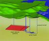
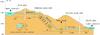
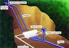
This project includes the construction of the upper dam in eastern Nagano prefecture, and the lower dam in southwestern Gunma prefecture, and connection of the two with a 6km long water tunnel. Power will be generated with an effective head of 653m, and a maximum water consumption of 510m3/sec. Construction began in May 1997 and the first plant, rated at 470MW, is scheduled to start operation in 2005.
The upper dam is a zoned fill dam with an impervious core, banks 136m high and 444m long, and a volume of 7.2Mm3. Work on the embankment of the dam began in October 1999, with approximately 90% complete today. The lower dam is a concrete gravity structure 120m high, 350m long, with a volume of 720,000m3. Concrete placing was completed in December 2001, and curtain grouting is currently under way.
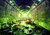
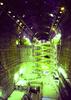
Four generator motors with the largest single output in Japan, as well as two transformers, will be placed in the underground power plant. A large cavern 216m long, 33m wide, 52m high, and with cross sectional area of 1400m2 and 220,000m3 excavated volume will be constructed at an approximate depth of 500m. The excavation of the top heading started in October 1998, and excavation of the cavern was completed in October 2000. Electrical equipment including power generators and pump turbines are currently being installed. The inclined shaft of the penstock is 961m long, has a vertical head of 714m, an inclination of 48º and a diameter of 6.6m.
Excavation by full face TBM was completed in April 2001, and installation of the steel penstock is now taking place. Construction of the tailrace tunnel is complete, and the headrace tunnel is currently being lined with concrete. By February 2003, 80% of the entire civil engineering work had been completed.
Construction technologies for large rock caverns
Since the late 1980s, many power plants of over 1GW have been constructed. Along with the increases in power output, the size of power plant caverns has also increased to accommodate longer headrace tunnels and larger head penstocks.
Technological developments in geological surveys, rock tests, stability analyses of large caverns, design, construction, and field measurement have played a major part in the development of rock engineering.
Site investigations and tests
Caverns of pumped storage plants measure up to 50m high, 30m wide, 250m long and 1500m2 in cross sectional area. Since they are much larger than ordinary tunnels (cross sectional area of approximately 80m2), thorough site investigations must be conducted to decide the location, shape, and arrangement of caverns and to evaluate stability.
Geological surveys and boring are first conducted at the surface of the site, and detailed geological surveys, borings, groundwater surveys, rock tests, and in-situ rock stress measurements are then performed by excavation of test adit. At construction sites where the overburden exceeds 500m, in-situ rock stress measurements are especially important to assess the mechanical stability of caverns.
Stability analysis of caverns and designing supports
In practice, finite element analysis is performed to analyse the stability of caverns, as well as slip line analysis and key block analysis that assumes discontinuities of rock.
In basic design, the shapes and directions of caverns are first determined. Power plant cavern supports are generally shotcrete, rock bolts, and prestressing rock anchors, which apply loads by tensioning strands. The specifications are determined for each of these support members.
Methods of numerical analysis for rock caverns either assume the rock to be a continuous body or use models of rock discontinuity.
Methods for evaluating the stability of caverns by continuous body analysis
The constitutive law of rock masses is broadly classified into elastic and elasto-plastic models. Elasto-plastic models are further classified into strain hardening, perfect elasto-plastic, and strain softening models. Conventionally, elasto-plastic models are widely used, but cannot appropriately evaluate the supporting effects of prestressing anchors during excavation. Strain softening models (which have been developed by the authors) have recently been used to evaluate the stability of power plant caverns. As strain softening analysis redistributes the overstress within the rock masses, it seems to accurately evaluate the effects of supports in strain softening and residual strength areas around the cavern.
Methods for evaluating the behaviour of rock masses by
discontinuous body analysis
Analyses of discontinuous rock masses are classified into methods that directly model discontinuities of rock and those that model the masses into pseudo equivalent continuous bodies. The methods that use direct models include the joint element model, discrete element method (DEM), rigid body spring model (RBSM), discontinuous deformation analysis (DDA) and key block method.
Observational Design and Construction System in Cavern Excavation of Underground Power Plants
The Kannagawa power plant is located 500m underground in sedimentary rock of the Paleozoic-Mesozoic layer. Since cavern excavation would take place under high rock pressure, an observational design and construction system was applied to rationalise the support design as well as to actively improve cavern stability. It was assumed that there may be concentrated stress areas where the in-site stress would reach over 25MPa maximum in the top of the cavern on the side of the tailrace tunnel and around the corners of the cavern on the penstock side, because the lateral pressure ratio inside the cross-sectional surface of the cavern is great due to the fact that the maximum principal stress axis are rotated from the longitudinal axis of the cavern.
A construction method was employed in which the spreading of loosened zones was minimised through early support measures such as allocating many PS anchors in this concentrated stress area, and smoothing the excavation of the wall surface as much as possible. Curvatures were put on the corner areas of the cavern of the power plant, and a smooth finish was applied on the wall surface.
Because of the rational support through this selective allocation of PS anchors, and because of the 3-dimensional-configuration effect by the rock acting as struts, the development of loose areas was suppressed. Further, by applying Acoustic Emission (AE) measurement and stress measurement, an observational design and construction system has been established, successively measuring the dynamic behaviour of the cavern during excavation while optimising support.
Forward thinking
The Kannagawa project can be viewed as a compilation of all the technologies developed over the past 30 years, ever since the construction of large-scale pumped hydro power projects first began. As it nears completion, it is worth thinking not only about technology transfer, but also about the creation and development of new wisdom based on the technologies accumulated to this day. This involves each specific technology as well as the creation and systemisation of ‘management’, which includes all kinds of technology in software terms as well. Also, it means advancing into a broader area from electricity/civil engineering to creating new social infrastructure, and also the shift from domestic to overseas.
A long time has passed since people began talking about the globalisation of the construction industry, and about bolstering international competitiveness to vitalise the Japanese economy. It is important to consider how to further expand the high technological skills that have been developed and accumulated domestically.
In southeast Asia and other surrounding countries, there is a strong demand toward development of electric power resources by IPP. We must clarify under what kind of vision we should further direct our accumulated technological skills as collective strength of our entire nation; what kind of technology management would be required to make effective use of our prominent technology overseas under widely differing conditions.
From this perspective, we need to continue to take on new challenges with great confidence in the future as well.
Author Info:
The author is Prof. Kenji Aoki, Dr. Eng. Department of Urban and Environmental Engineering, Graduate School of Engineering, Kyoto University, Japan. For more information, email: aoki@kumst.kyoto-u.ac.jp
The author would like to extend gratitude to the people in Underground Construction Group at Civil and Construction Technology Center, Construction Department, TEPCO and to the people at the Kannagawa Hydropower construction site for their kind and generous cooperation.