Over-performing underground
10 January 2008Even before the Kops II pumped storage plant in Austria goes online, some remarkable accomplishments have taken place in one of the world's largest rock cavities
As the major underground components of the Kops II project in Austria took shape, excavation techniques were pushed to the limit, logistics were tight and flexible solutions had to be found for concreting and lining of the rock caverns. The key to success was the intense work preparation throughout the project implementation phase, which resulted in significant accomplishments in constructing the civil works of the pumped storage plant.
In the period between November 2004 and December 2005, a total volume of 125,000m3 was excavated in the powerhouse and transformer caverns. The excavation works for the tunnels and shafts – 1782m in total – were performed in parallel to the excavation works for the caverns, and amounted to a total of 78,000m3. The performance level attained with respect to the lining works is also remarkable. Over a period of 18 months, approximately 48,000m3 of concrete was placed simultaneously with the numerous lining and backfilling works in the tunnels, shafts and other auxiliary structures.
Scheduled for completion in 2008, the Kops II pumped storage scheme is located at the end of the Montafon Valley in the Austrian Province of Vorarlberg. Three 150MW, highly flexible units will be used for both turbine and pump operation, and operated under rapid control. The existing Kops Lake is being used as an upper storage reservoir and the existing Rifa balancing reservoir for lower storage.
All major components of the scheme are underground and total investment costs are approximately US$535M. Construction work began in September 2004 and the first generating unit is due to go online soon.
Key features of power producer Vorarlberger Illwerke’s project include:
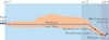
• Pressure tunnel – the 5.5km long pressure tunnel forms the connection between the Kops Lake and the beginning of the pressure shaft. The tunnel was excavated using a double-shield tunnel boring machine (TBM);
• Pressure shaft and surge chamber – the 1.1km long pressure shaft was excavated by TBM, advancing from bottom to top. Featuring an inclination of 80%, the pressure shaft overcomes a difference in height of 700m;
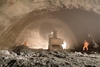
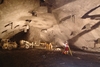
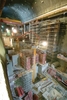
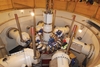
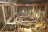
• Powerhouse cavern – one of the largest engineered rock caverns, at present. To accommodate the 38m-high generating units, the cavern is 88m long, 30.5m wide and 60.5m high, and the excavated volume is approximately 113,000m3;
• Transformer cavern – with an excavation volume of 10,000m3, this large rock cavity is 35m long, 16m wide and 19m high;
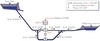
• Tailrace structure – this includes the inlet and outlet structure in the Rifa reservoir, the 267m long tailrace tunnel, the tailrace surge chamber of 12m diameter and 31m high shaft, plus a 47m-long chamber. Three pressure chambers, each 45m long, are linked to the tailrace via a 77m-long connection tunnel;
• Tunnel systems – totalling almost 1800m in length with cross-sectional areas of 12m2-52m2, and declines and inclines of up to 37%. Technical limits were pushed and many tunnels were too short to allow gearing up for high production rates.
Geology & Procurement
All parts of the Kops II project are built within the Silveretta crystalline rock series and these consist mainly of solid, hard strata, such as amphibolite, horblende gneiss and others types of gneiss, although some less solid mica schist was also found.
In general, the excavation benefited from favourable rock conditions, although rather more difficult ground conditions were met in some locations. Depending on particular rock mass quality, structural support of the excavations included rockbolts, shotcrete, wire mesh and steel arches.
Kops II was the first project in Vorarlberg that required an environmental impact assessment (EIA) to identify and evaluate the impact of the scheme and look at possible mitigation measures. As a result, stringent requirements were placed on the client to have the project built by ensuring environmentally-friendly transport of spoil as well as compliance with air, noise and water pollution thresholds. Independent checks of performance were carried out by third party firms.
To undertake the works, the project was divided into three contract sections. The powerhouse and transformer caverns, the associated tunnels and the tailrace structure have been built in the Lot 3 contract on the project. The Lot 3 contract is tightly limited to the downstream end of the project layout, at the side of the valley floor.
Immediately upstream of Lot 2 is the pressure shaft and surge chamber works, which have been undertaken in the Lot 2 contract and were excavated within the steeply sloping valley side. Lot 1 is the longest contract in terms of geography. It is for construction of the headrace tunnel from the upper reservoir, and runs along the top of the valley side.
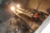
Excavation
The excavation of the powerhouse and transformer caverns was complicated by various limiting factors due in part to procurement requirements and also to logistics. The bores began by using the existing pilot tunnel, which is to be a cable tunnel in the operational phase of the project. It had to be enlarged to provide space for two ventilation ducts and concrete mixer trucks. A 170m long muck removal tunnel, inclined at 24% and having a cross-sectional area of 22m2, was also driven.
Branching off the pilot tunnel was a newly built access tunnel to open up the transformer cavern and the powerhouse cavern. Upon completion of the transformer cavern’s top heading, the powerhouse cavern’s top heading was excavated via two side drifts, access to the one on the right being gained via a previously built cross passage. The excavation was not easy despite the apparently favourable geological conditions.
The top heading of the powerhouse cavern had a cross-sectional area of 220m2 and was divided into three sections. The core of the top heading could be removed upon installation and pre-stressing of the 43m long strand anchors in the side drifts, which had working loads of 1250kN, could be undertaken. The initial excavation support employed after every round of advance consisted of Swellex anchors. The 16m long rockbolts and a second layer of shotcrete followed in the second round of advance.
Due to the limited range of the lifting platforms, the anchor heads of the strand anchors were capped with fire and blast protection covers and the two-layer lining shotcrete was applied before the bench excavation was started.
Upon excavation of the first bench, the concrete beams for the crane were installed and subsequently supported by 68 strand anchors. To protect the concrete beams from possible damage caused by blast vibrations during the subsequent bench excavation, the concrete beams were placed on a 1.5m-high frame structure.
Spoil removal from the bench excavation in the cavern was via a conical-shaped glory hole and a muck tunnel with a rock crusher and discharge conveyor loading onto an 830m long by 800mm wide conveyor belt. The mucking out system was designed for 220tons/hour but effectively handled up to 400tons/hour.
Geotechnical conditions made it necessary for the three large, compressed air surge chambers (each with a cross-sectional area of 66m2) to be excavated and supported before each respective bench level was reached. The two remaining ground pillars – each 11m wide and located between the chambers – were strengthened by chamber-to-chamber anchors to reduce stresses and strains, thereby minimising adverse effects of load redistribution on the large cavern opening during excavation. For reasons of layout geometry, it would not have been possible to add further anchors later to the top heading of the cavern, should there be a need due to levels of deformation.
Originally, the pressure chambers were to be built via the muck and tailrace tunnel and the bent connection tunnel. However, construction logistics dictated that, instead, they should be advanced by three inclined tunnels running through the powerhouse, from the headrace to the tailrace system. The pressure chambers were constructed at the same time as the crane beams in mid-2005.
A relatively low rock mass strength was observed when excavating the cable cellar of the transformer cavern. Despite extremely careful blasting works, the remaining vertical side walls had to be excavated and scaled manually and in sections, and still had to be supported and anchored. By the end of November 2005, all bench levels (10 in total) had been excavated. This was achieved despite the fact that, at the pressure chamber level, the normal bench height of 5m – the optimum to achieve a reasonable balance between drill and blast excavation, mucking out and support installation sequencing – had to be reduced to only half as much.
Also, unfavourable dipping and joints uncovered in blasting the central bench often resulted in shopping surfaces. As a result, wider side benches were required, at 5m-6m, which was up to 50% more than planned. The side benches were also drilled horizontally to help minimise overbreak.
The remaining excavation works, such as the dewatering pump sumps and local pits, and the tailrace tunnel, were completed by December 2005. The three inclined shafts for the pump mains were excavated top down, allowing the horizontal pump main tunnels to hole through when each respective bench level was achieved. For the tailrace, the tunnel was excavated below a road, river and dam. A 90m long soft rock section below the Ill river towards the Rifa reservoir was excavated using two groundwater lowering wells and pipe arch protection.
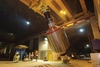
Concrete linings
At the tender stage of the project, the intention was that pumping was not to be used due to the large quantities of concrete required in the caverns and expected high temperatures. It became evident that placing concrete by crane and bucket might put the required construction schedule at risk. Additionally, the commencement of lining works in the powerhouse cavern coincided with the installation works of the hydro mechanical equipment, and there was also limited use of the auxiliary construction crane. As a consequence, agreement was reached with the client to use pumpable concrete.
Two concrete distribution booms were employed to easily reach all parts of the powerhouse cavern. The concrete mix was modified and adjusted several times to keep the temperature low and minimise shrinkage cracking. An in-situ concrete mixing plant was also installed to allow independence and flexibility on the construction site.
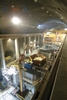
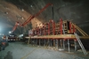
Another vital aspect of the lining works in the logistics-intensive environment of the powerhouse cavern, which was divided into seven activity levels each of which had 45 structural components, was to reduce the stock of formwork to a minimum. The structural components were large and resulted in high pressures from slabs up to 4m thick and walls up to 8.5m high. Some individual structural components had concrete volumes in the range of 400m3-600m3.
The start of the lining works in December 2005 was also when construction work began on the first concrete foundations in the powerhouse cavern. The construction sequence was arranged so that the assembly/installation and concreting works were generally carried out in a staggered approach between the locations of the generation units. All other lining works were either done at the same time or — depending on the technical feasibility — had to overlap with the main lining works.
Works in the transformer cavern were done to compensate for a longer interruption or a total standstill of works in the powerhouse cavern. Key dates in the construction programme at the powerhouse cavern were influenced by the installation of the tailrace crane support structures and for operational start-up of unit no. 3. The crane support structures were needed to mount the heavy-duty crane, which in turn was essential for installation of the hydro mechanical equipment.
Apart from the impressive dimensions of the structural components, which sometimes led to concreting times of more than 24 hours, the demands resulting from mechanical equipment installations were a major challenge. In particular, unlike previous projects, the steel structures such as bearings, rails and their structural components were concreted in one go. To successfully pursue this strategy put special demands on accuracy of positioning for the steel structures.
Assembly of the steel reinforcement bars into densely packed, three-dimensional cages for concreting was more time-consuming than anticipated. With numerous structural components being either fully or partially lined with steel, ensuring accurate reinforcement arrangements called for intensive cooperation and coordination with the firms supplying the hydro mechanical equipment.
For project schedule reasons, all auxiliary structures had to be completed at the same time as the lining works of the powerhouse cavern. In addition to the concrete backfilling of the steel lining and the installation of concrete linings using shutters, the auxiliary structures to be constructed included several highly complicated transition and narrowing or widening sections. Formwork elements for those sections were produced on the project site and successfully installed. The 40m high surge chamber shaft was slipformed.
Above ground
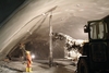
A special challenge was the limited period available for surface construction works at the inlet and outlet structure in the drained Rifa lower reservoir. The time window to build the structure was the low water period between January 2006 and May 2006, as defined by the client.
However, the extremely cold and long winter saw temperatures drop to –15 °C and the teams were pushed to their limits. With the frost zone extending up to 1m below the surface, the contractor used three to five layers of frost protection fleece to shield the concrete. As the date for the refilling of the Rifa reservoir was at the beginning of June 2006, postponement of the works was not an option.
At peak times, more than 130 skilled workers were on site and all works were performed continuously in day and night shifts. Overall, thorough preparation and the strong commitment of all the specialists involved has been key to the successful underground construction challenge at Kops II.
This article is based on a paper by Helmut Westermayr and Michael Tergl of Beton-und Monierbau, which was presented at the Rapid Excavation and Tunnelling Conference. IWP&DC thanks the authors and the client, Vorarlberger Illwerke AG, for their kind permission to reference the paper, and for providing illustrations for the article. Thanks also to the project manager of Kops II, Dr Ernst Purer of Vorarlberger Illwerke AG.