Seismic performance of CFRDs
28 March 2007Martin Wieland and R Peter Brenner present a qualitative assessment of the seismic performance of concrete face rockfill dams under strong ground shaking, and discuss possible problems and deficiencies
In the last twenty years concrete face rockfill dams (CFRDs) have been built in increasing number. The reasons for this development are mainly of economic nature. However, because the number of these dams is still relatively small and since most of them were built within the last decade (many more projects are on the drawing boards – most of them in China), experience on the actual performance of these dams under earthquake loading conditions is still very scarce. We have to realise that not all seismic problems pertaining to large dams have been solved. Every time there is another strong earthquake, upgrading the design criteria and design concepts may become necessary. This applies in particular to more recent types of structures such as CFRDs. In addition, there is also very little experience with the seismic performance of grout curtains and diaphragm walls, which form an important part in any dam project.
In the subsequent sections some of the relevant earthquake aspects of CFRDs are briefly discussed without going into the theoretical details of possible mathematical models. Before an attempt is made to solve a particular problem, it is important to take an integral look at the phenomenon first, otherwise important aspects may be overlooked. This is particularly true for new types of dams.
An overview on the seismic aspects of CFRDs is given in the General Report of the 21st icold Congress (Wieland, 2003). The state-of-practice on earthquake safety of dams was discussed in some 75 reports. Also at the 13th World Conference on Earthquake Engineering (Wieland and Brenner, 2004) some 65 papers were concerned with seismic aspects of dams. However, the information on the performance of CFRDs under seismic loading is still poor. Once sufficient experimental and/or observational information has become available, the current design practice may have to be reviewed.
Main features of CFRDs
CFRDs consist essentially of a zoned rockfill embankment sealed on the upstream side by a thin concrete slab. Face support and transition zones are provided immediately beneath the concrete slab. The concrete face, together with the perimetric joint and the plinth, are the elements which provide the watertightness of the dam above ground.
The main advantages of CFRDs as compared to conventional earth core rockfill dams may be summarised as follows:
•Steep slopes: The high friction angles achieved with compacted rock and gravel fills and the absence of an impervious zone with high pore water pressures during rapid drawdown, enables designing the dam body with steeper slopes and reduced volume.
•Speed of construction: Fill placement is relatively straightforward and independent of weather conditions. Compaction of the rockfill during rainfall is even advantageous as it reduces the need for wetting the material being placed. Fill placement can start before construction of the grout curtain is completed.
•Stabilising effect of water load: The resultant of the water load is transmitted into the foundation upstream of the dam axis.
•Economy: Because of smaller fill volume, resulting from steeper slopes, a CFRD is usually more economic than an earth core rockfill dam provided suitable rockfill material can be obtained in the vicinity of the dam.
•Earthquake stability of rockfill: Since the rockfill is essentially dry, earthquake shaking cannot generate excess pore water pressures. With the absence of pore water pressures and the high shear strength of compacted rockfill, this dam type is considered inherently resistant to seismic loading (Cooke, 1991). Possible failure modes that were considered are (1) sliding of shallow material along planar or nearly planar surfaces and (2) wedge failure or deep-seated rotational failure (Seed et al., 1985).
However, there are certain features with these dams which should not be overlooked, i.e.:
•Vulnerability of perimetric joint: The perimetric joint connecting face slab and plinth (or toe slab) is the most critical element in the dam. When it ruptures leakage will occur. However, by providing adequate filter zones the washing out of foundation material can be prevented.
•Crack development in the concrete face slab: Due to deformations in the rockfill the concrete face slab will experience cracking. However, experience with existing dams has shown that properly compacted rockfill can minimise deformations and also crack development. In particular, zones in the upstream part of the embankment, including fine and coarse-grained transition zones under the slab, should be constructed of material of low compressibility. The ideal material is alluvial gravel if available (Mori, 1999). With compacted gravel fills very high deformation moduli can be obtained.
•Deformations in CFRDs: Experience with carefully monitored dams of compacted rockfill revealed that crest settlements are very small, i.e. in the range of about 0.1 to 0.2% of the dam height and may essentially be completed within three to five years. Dams in narrow valleys can be affected by arching and the settlement process is delayed. Strong earthquakes can produce further settlements. They are estimated to be of the order of 0.5 to 1m. However, this magnitude of crest settlement is no problem to dam safety provided the dam has been designed with an adequate freeboard.
•Limited experience in design and construction: Concrete face rockfill dams higher than about 30m have been built since the early 1920s (Cooke, 1985). However, in those dams the rockfill was placed by dumping and consequently the fill was loose with considerable potential for settlements upon shaking. Modern CFRDs with compacted rockfill became of interest in the late 1960s and by now there is a great number of such dams, especially in Brazil and China. But in many countries where dam construction is sporadic, contractors do not have the experience in building such a dam and in order to engage a local contractor another dam type may be chosen by the owner.
•Aging of concrete face: The concrete face is not a geomaterial and will be affected by aging processes much faster than earth and rockfill materials. The concrete face and the joints with waterstops between the slabs may need repair during the lifetime of the dam.
The above list demonstrates that CFRDs have special features, which must be properly taken into account in a successful design. At the upstream toe of the dam there is a very high hydraulic gradient, usually roughly estimated as the water head divided by the width of the plinth. For foundation conditions on good quality (slightly weathered) non-erodible rock, this gradient can be as much as 20 whereas for plinth foundations on weathered rock, residual soil etc. the gradient should be reduced to about 10. Still these gradients are much higher than those recommended for earth core rockfill dams where the width of the core base should not be less than about one fourth of the water head. Similarly, modern arch dams have a base with a width not more than one fifth of the water head. Hence, gradients in CFRD dams are about 2 to 5 times higher than those in earth core rockfill or arch dams respectively, depending on the quality of the foundation material.
Seismic safety aspects
According to Sherard and Cooke (1987) CFRDs have no problems with safety during and after a strong earthquake. There is no pore pressure in the free-draining, heavily compacted rockfill and earthquakes will produce only small deformations. However, there is no case history of a modern CFRD that was shaken by a very strong earthquake. The 85m high Cogoti CFRD in Chile, completed in 1938, has been shaken by several earthquakes (Arrau et al., 1985). The 1943 Illapel earthquake with a magnitude of 7.9 and an epicentral distance from the dam site of about 90km produced a peak ground acceleration (PGA) of 0.19 g. This dam was constructed of dumped rockfill without any water sluicing. There was no damage to the face slab which had a thickness varying from 80cm at the base to 20cm at the top. The earthquake produced an instantaneous settlement of the crest of 40cm.
A 17m high, CFR saddle dam on the right abutment of Sugesawa dam in Japan was shaken by the 6 October 2000 Tottori earthquake. The PGA measured on the right abutment of the saddle dam was 0.36 g. No damage was observed (Matsumoto et al., 2001).
Both case histories are from regions of high seismicity and depending on the location of major CFRDs relative to geologic structures much higher ground motions can be expected at sites of high dams. CFRDs are different from conventional rockfill dams because (1) the concrete face is a much stiffer element than the compacted rockfill zones, and (2) the concrete slab is impervious and acted upon by the hydrostatic pressure, causing high compressive stresses on the rockfill particles in the lower part of the face zones. Therefore, upstream slope stability is ignored in analyses.
Earthquake analyses of CFRDs in the past have focussed mainly on settlement predictions of the crest and deformations of the dam body and the stability of the downstream slope. Numerical analyses mostly employed two-dimensional models and methods included simplified procedures, equivalent linear analysis, effective stress non-linear finite element or finite difference analysis (Bureau et al., 1985, 1997; Seed et al., 1985; Seco e Pinto, 1996). There is a general consensus that for well-designed and well-compacted dams, such as modern CFRDs, the use of simplified procedures or the equivalent linear analysis in combination with Newmark’s sliding block analysis of slopes, produces a safe design.
The influence of the hydrodynamic water pressure on the face slab has been modelled in various ways either as an added mass or by introducing fluid-solid and fluid elements in the finite element model. The hydrostatic pressure increases the effective stress in the rockfill next to the slab and thus increases its stiffness. This effect is compensated by the hydrodynamic pressure so that the dynamic response is not changed significantly by the effect of the hydrostatic pressure.
Little attention has been paid to the behavior of the face slab although it is generally agreed that during a strong earthquake the face slab is likely to crack. But potential cracking and subsequent leakage do not impair the safety of the dam because the amount of leakage water that would pass through the structural cracks and the semi-pervious transition zone can easily be discharged by the free-draining rockfill downstream of the slab (Sherard and Cooke, 1987). There have been many cases in which large quantities of water have passed through compacted rockfill (from construction floods or major leakage through the face) with no significant effects, i.e. no settlement caused by through-flow. Sherard and Cooke (1987) explain this by the high contact stresses existing between the rockfill particles which produce friction forces that are much higher than the hydraulic drag forces. Only loose soil grains in the voids of the rockfill can be washed out by leakage water.
Since cracks in the slab are only an economic problem in that water is lost, there is little interest in sophisticated seismic analysis of the rockfill/slab system.
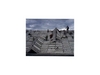
For the assessment of the seismic performance of the concrete slab of CFRDs, the analysis of the effect of the cross-canyon earthquake component is mandatory to arrive at realistic results. The deformational behaviour of the almost rigid concrete slab for in-plane motions is very different from that of the rockfill zones in the embankment, thus the motion of the rockfill in crest direction will be restrained by the face slab. Therefore, for cross-canyon vibration, the stiff concrete face will attract seismic (membrane) forces from the dam body. Hence, very high in-plane stresses may develop in the face slab. Shear failure and/or spalling of concrete may occur at the highly stressed joints. In the extreme case, slab elements may be pushed upwards as shown in Figure 1. Moreover, joints may open under tension.
Figure 1 shows the buckling (pushing up) of elements of a canal lining produced by the 1999 Chi-Chi earthquake in Taiwan and in Figure 2 the sliding of concrete elements of a canal lining is depicted. These are figures which may show some of the failure mechanisms that could occur in CFRDs.
With the face slab elements being much larger and heavier, a scenario of such a scale (Figure 1) is not very likely but the mechanism can be the same. It is concluded that the analysis of the cross-canyon earthquake effect be considered in the seismic analysis of CFRDs in order to clarify the magnitude of dynamic stresses in the face slab and the response of the slab to these forces. It is also recommended to supplement dam instrumentation with strong motion instruments, especially in regions of high seismicity and in large CFRDs.
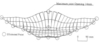
The opening of vertical joints in the face slab during earthquake loading was studied by Harita et al. (2000) with a three-dimensional elastic finite element model which had non-linear spring elements at the slab joints. A loading history of about 10 s duration and with a horizontal PGA of 0.18 g produced a joint opening of about 15mm at the top of the slab (see Figure 3). Joints repeatedly opened and closed during seismic loading and the slab movement followed that of the dam body.
Seismic aspects of diaphragm walls and grout curtains
Diaphragm walls
Diaphragm walls are used as sealing elements in embankment dams on soils or on very pervious rock and were initially made of ordinary reinforced concrete. Today, preference is given to plastic concrete. The wall should have a stiffness of similar magnitude to that of the surrounding soil or rock in order to prevent the attraction of load when the soil deforms after dam construction. The dynamic stiffness of both the wall and the surrounding soil or rock, however, is higher than the corresponding static value.
Although earthquakes may still cause significant dynamic stresses in the plastic concrete cut-off wall, sufficient ductility of the plastic concrete will minimise the formation of cracks. The highest stresses in the wall are expected to be caused by seismic excitations in cross-canyon direction.
An upper bound estimate of the in-plane stresses in a rigid diaphragm wall can be made by assuming that a cross-canyon motion causes sliding between the concrete diaphragm and the soil, mobilising the whole frictional resistance. As under full reservoir the normal stresses on the wall at the downstream interface are high, the friction resistance is also rather high. At the upstream interface, the normal stresses and the frictional resistance are much smaller. In this case stresses occur, which could damage the concrete of the diaphragm wall.
In the case of diaphragm walls made of plastic concrete with a low dynamic modulus of elasticity, the seismic stresses should be smaller than in a rigid diaphragm wall, but the strength properties of plastic concrete are also inferior to those of ordinary concrete.
Hebgen dam located in Montana, US, which has a concrete wall in the centre of the dam, was subjected to the1959 Hebgen Lake earthquake and was overtopped due to seiches in the reservoir. The poorly compacted shell material settled significantly relative to the rigid concrete wall but no concrete wall damage was reported. The overall size of the diaphragm wall was small and thus any seismic stresses were also rather small, moreover, any small to moderate size crack in the concrete wall may have been plugged by silty materials covering the face slab in its lower part.
The experience with the seismic behaviour of diaphragm walls is still very limited and additional investigations and observations are necessary.
Grout curtains
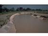
In general, it is assumed that the grout curtain in the rock foundation is not vulnerable to earthquake action. However, due to dynamic soil-structure interaction effects, joint movements in the foundation rock, and fissures in the dam foundation, etc. the grout curtain can still be damaged locally during major earthquakes. In the case of the Sefid Rud buttress dam in Iran, which was severely damaged during the 21 June 1990 Manjil earthquake (magnitude 7.4 earthquake with epicenter close to the 106m high dam) some local damage could not be excluded along existing discontinuities (Figure 4) in the dam foundation (Eftekhari and Jalalzadeh, 2003). Local changes in uplift pressures and drainage water were observed. As a remedial measure, additional grouting works were performed and the foundation drainage system was rehabilitated.
The earthquake damage to grout curtains may be assessed based on sudden changes in the uplift pressures and in drainage water. In Japan, changes in uplift pressure and seepage from the drainage holes have been observed after earthquake shaking. However, these changes did not imply damage of the grout curtain.
Very little is known about the seismic performance of grout curtains. Grout curtains in rock essentially fill fissures and joints. With this they become part of the rock. Damage to such curtains can only occur if movements take place in the foundation rock treated by the grout curtain. It is recommended that seismic effects on grout curtains be considered in the design and seismic safety assessment of dams.
Seismic damage
Concrete face
The hydrostatic water pressure is pressing the concrete face on to the face support and transition zone materials. Thus the shear resistance against sliding of the concrete face on these materials is also growing with increasing water pressure. At the same time the water pressure prevents the separation of the concrete face from the soil. Therefore, the possible damage patterns of a concrete face shown in Figures 1 and 2 are more likely to be expected in the uppermost parts of the dam and not at greater reservoir depths providing the joints are working properly.
At greater water depth local joint damage in the concrete face due to compression and shear but also joint opening, as shown in Figure 3, must be expected, leading to increased leakage losses. Widening of existing cracks within the concrete slab elements also has to be expected all over the concrete face.
Due to the fact that the reinforcement is placed in the middle plane of the slab the stiffness will reduce significantly once cracks have formed. Also the crack width will be larger at the surface as in the case where the reinforcement would be placed in two separate layers near the surfaces of the slab. Although a large concrete cover is needed from the durability point of view, standard reinforcement of the elastically supported slab elements would be beneficial.
After strong ground shaking, leakage is expected to increase significantly. It should be shown in the seismic design of the concrete face (as a worst case) that the complete failure of a slab element does not have a negative effect on the safety of the dam and that such a failure scenario can be accepted.
Diaphragm wall
During an earthquake a concrete diaphragm wall – even those made of plastic concrete – will have a dynamic stiffness, which is of the order of that of normal concrete. Due to this fact the diaphragm wall will attract a substantial amount of seismic forces especially in in-plane directions (membrane forces). As the dynamic strength of plastic concrete does not increase at the same rate as the dynamic stiffness, damage of the low strength diaphragm wall is likely to occur.
The consequences of such damage are leakages in the foundation. The consequences of these leakages depend on the type of foundation material and include increased uplift pressures along joints in foundation rock (causing stability problems etc.) and most importantly internal erosion in some soils. Minor concrete cracks may be plugged by fine material and seepage may reduce within a short period after an earthquake.
Therefore, in the seismic design of diaphragm walls the consequences of local wall failure have to be addressed as well.
Grout curtain
Grout curtains are mainly used in rock whereas in soil materials diaphragm walls are preferred today. During an earthquake existing cracks and fissures will open and close and new cracks may be formed. These cracks will generally be small unless an active fault is present where larger displacements may take place. This will lead to increased leakage after an earthquake. Such phenomena have been observed in a number of dams, even in cases where the earthquake has occurred at greater epicentral distances. This seepage leads to increased uplift pressures, which may have a detrimental effect on the stability of a dam. Minor cracks and fissures may be plugged by fine material and seepage may reduce within a short period after an earthquake.
Therefore, in the seismic design of a grout curtain the consequences of local cracks and increased seepage also have to be addressed.
Conclusions
Concrete face rockfill dams are economically attractive alternatives to conventional earth-core rockfill dams. Since there exist nearly no observations about the response of these dams to seismic loading, their seismic performance must be studied carefully taking into account all existing information.
Well-designed and properly compacted CFRDs on rock foundations are considered safe under the strongest earthquake loading. This is because the width of the cracks in the face slab that may develop as a result of high dynamic stress and deformations, predicted from a traditional two-dimensional dynamic analysis of the highest dam section, are relatively small and thus the resulting leakage does not impair the safety of the dam. However, the behaviour of the concrete face during a strong earthquake is largely unknown, especially when looking at the cross-canyon excitation, which up to now has been largely ignored because of its complexity. The large membrane forces in the slab generated by the cross-canyon excitation may cause local buckling at the joints, rupturing of water stops and/or movements of individual slab elements as rigid body. If such movements take place then the flow across the slab will greatly exceed the leakage through structural cracks in the concrete slab. Besides, in narrow valleys the three-dimensional deformations of the dam due to an earthquake excitation in valley direction may lead to damage of joints (and compression and shear stresses in joints).
The largest CFRDs under construction have heights exceeding 200m. Local damage of the concrete face (especially large joint displacements) due to earthquake action may drastically increase leakage losses. For the safety of very high CFRDs it is important to know if the consequences of joint leakage (with large opening) under high hydrostatic pressure are similar to those under low to moderate pressures. As up to now no major CFRD has experienced ground shaking similar to that expected during the maximum credible earthquake, the above scenarios are still of hypothetical nature.
Diaphragm walls and grout curtains should therefore also be considered in the overall seismic design of a dam as damage caused to these elements may have detrimental effects on the overall safety of the dam after a severe earthquake.
Figure 1: Buckling of canal lining elements caused by the 21 September 1999 Chi-Chi earthquake in Taiwan Figure 1 Figure 2: Irrigation canal lining damaged during the 21 June 1990 Manjil earthquake in Iran (rigid body movement of concrete elements) Figure 2 Figure 3: Deformation of concrete slab obtained fron dynamic analysis (Harita et al., 2000) Figure 3 Figure 4: Existing crack in foundation gallery of Sefid Rud buttress dam re-opened after the 1990 Manjil earthquake. Crack is assumed to extend into the dam foundation and grout curtain. Water was splashing into the gallery under high pressure. Figure 4 Author Info:
Martin Wieland, Chairman, ICOLD Committee on Seismic Aspects of Dam Design, Electrowatt-Ekono Ltd (Jaakko Poyry Group), Zurich, Switzerland. Email: martin.wieland@ewe.ch; and R Peter Brenner, Consulting Engineer, Weinfelden, Switzerland. Email: Brenner.gde@freesurf.ch