Taking on the challenges at Dibang
19 September 2008M M Madan presents an overview of the proposed 3000MW Dibang multipurpose project in Arunchal Pradesh, India, and describes some of the challenges that engineers are likely to face when building the scheme
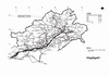
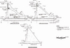
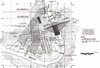
The 3000MW Dibang project is a multipurpose scheme being developed to harness the hydro potential of the river Dibang, while also mitigating flooding problems in the downstream area. The project is to be located in the Lower Dibang valley district of Arunachal Pradesh, near the village of Munli, about 43km upstream of Roing and 1.5km upstream of the confluence of the Ashu Pani and Dibang rivers.
The project comprises the following main components:
• Five 12m diameter horseshoe shaped concrete lined diversion tunnels varying from 1175m to 1325m in length aggregating to total length of 6260m.
• An upstream RCC cofferdam and downstream earthfill cofferdam with six 4 x 4m construction sluices envisaged within the dam body to supplement the diversion capacity when the dam has been raised to considerable height.
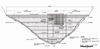
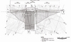
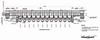
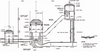
• A 288m high concrete gravity dam with two level orifice type spillways consisting of seven bays of 6m x 8m at the lower level, and four bays of 9m x 12m at the upper level.
• Six intake structures – one for each headrace tunnel with gate opening size of 8m (W) x 9m (H)
• Six 9m diameter horseshoe shaped concrete lined headrace tunnels varying from 300m to 600m in length aggregating to a total length of 2700m.
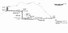
• Six 7.5m diameter, 184.8m high circular steel-lined pressure shafts each bifurcating into 5.2m diameter penstocks at the lower limb to feed two units of the powerhouse.
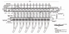
• An underground powerhouse containing 12 x 250MW units with MIV cavern of 17m (W) x 26.1m (H) x 277.8m (L), a powerhouse cavern of 24.5m (W) x 54.8m (H) x 382.8m (L) and a draft tube Gate ,GIS and transformer cavern of 19m (W) x 31.5m (H) x 325m (L).
• Six 9m diameter horseshoe shaped concrete lined tailrace tunnels varying from 320m to 470m in length
• Pothead yard of size 300m x 100m
Hydrology
The catchment area of the river Dibang at the dam axis is about 11276km2, and the submergence area at full reservoir level is 40.09km2. The average annual rainfall is 4405mm while maximum and minimum temperature is 45°C and 2°C respectively. The rainy season in the area is from June to October.
Geology of project area
Dibang multipurpose project is located in the Mishmi hills of Arunachal Pradesh. In the project area, the rocks belonging to Ithun Formation and Hunli Formation of Palaeozoic to Precambrian age are exposed. The Ithun Formation comprises of inter banded sequence of quartzo feldspathic gneiss, feldpathic amphibole-biotite gneiss, schist & phyllites, pegmatite gneiss, while the Hunli Formation consists of phyllites, quartzitic phyllite and slates intruded by volcanic rocks. The contact of the two formations is inferred as a thrusted contact, which passes through the tailrace tunnel outlet area and intersects the main access tunnel and diversion tunnel near the outlet end. However, apart from the above, all the major structures (dam, headrace tunnels and powerhouse) are located in Ithun Formation.
The project is located in Zone-V of the seismic zoning map of India. Three northwest–southeast trending tectonic thrusts – Mishmi thrust, Tidding suture zone and Lohit thrust – are located in close proximity to the project area. While Mishmi thrust is located south of the project, the other two are located north of dam site.
Dam
The height of the concrete gravity dam is 288m from the deepest foundation level and the length of the dam at the top is 816.3m at el 550m, with 154m of overflow section. The spillway is designed for a 19,000m3/sec discharge. Two level orifice type spillways have been proposed comprising of four bays of opening size 9m x 12m with crest at el 500m, and seven bays of opening size 6m x 8m with crest at el 455m. At the dam site, rocks comprising of amphibole bearing feldspathic biotite gneiss are exposed on both the banks. These rocks are highly folded, weathered and sheared in places. The subsurface explorations carried out at the dam site indicate that the left bank is comparatively weaker than the right bank. As the height of the dam is 288m from the deepest foundation level, the overall height of the open excavation owing to stripping in the abutments will be in the order of 300-350m. In view of the high cuts, valley dipping joints and sheared nature of rock, cautious excavation with adequate support will be required.
Overall, the dam site is explored by 15 drill holes and four drifts. The maximum depth of overburden in the riverbed is 25m. The bedrock is traversed by shear zones/fractured zone and schistose bands, as revealed by the drill holes. Such zones will require proper treatment.
The total quantity of rock excavation in the dam abutments and river bed has been estimated as 5,583,600m3, which is required to be completed over a period of 23 months. Further the dam work also involves 16,100,000m3 of concreting to be completed in a period of 46 months.
The fact that the dam on its completion will be one of the world’s highest concrete gravity dams in a demanding geological environment, an innovative planning, design and construction methodology is a necessity for this project.
Diversion tunnel
Five diversion tunnels of 12m diameter and lengths varying from 1175m to 1325m are proposed on the right bank of river. The maximum cover over the diversion tunnel is 380m. The diversion tunnels are expected to negotiate through highly folded sequence of rocks. Due to the presence of thrusted contact between Ithun and Hunli formation, poor to very poor rock condition are expected in all the diversion tunnels near the outlet portion. The outlet area is covered with thick overburden and weathered rock ranging from 15 to 20m which will need to be removed in order to form the outlet portals. Damp to dripping conditions with isolated pockets of heavy seepage are expected. To sum up, a major part of the tunnel would be driven in fair to good quality rock with substantial portions of poor to very poor rock conditions due to intersection of thrust and other shear zones. The intake portals will also require heavy cutting to ensure overall stability of the structure.
Water conveyance system
The water is lead to the headrace tunnel through six intake structures with invert at el 465m, i.e. 25m below the minimum drawdown level. An inclined type trashrack structure is proposed at the entrance of the intake structure. Six 9m diameter horseshoe shaped concrete lined headrace tunnels are provided. The length of the tunnels vary from 30m to 600m, amounting to a total length of 2700m with design discharge of 237.80m3/sec each. The total quantity of surface excavation of the portals in the headrace tunnel works has been estimated as 860,200m3/sec. This work is scheduled to be completed over seven months, with the underground excavation expected to take 10 months. The intake structure also involves 552,900m3/sec of concreting to be completed in 10 months, with six underground pressure shafts proposed for the right bank.
The combined intake location is about 200m upstream of the dam axis. At this site, the slope is covered by overburden which will need to be removed for proper foundation of intake structures. The bedrock is anticipated to be folded gneissic rock with intermittent schist bands. The headrace tunnel is expected to be driven through highly folded and closely to moderately foliated rocks of Ithun Formation. Major portions of the tunnel would be driven almost oblique to foliation plane. In view of the heavy precipitation in the area, moist to heavy dripping conditions inside the tunnel cannot be ruled out. In addition the weak mica-schist bands and shear zones may also pose problems during excavation. As such, adequate support arrangement will be required. Overall mainly fair to good rock with some reaches of poor to very poor rock condition is expected during tunnel excavation.
At the downstream of each headrace tunnel, a 7.5m diameter steel lined vertical pressure shaft 184.8m high will be provided with further bifurcates into two penstocks to feed two units. The pressure shafts are expected be housed in strong to medium strong quartzo-feldspathic biotite gneiss with occasional bands of biotite chlorite schist. Overall, the rock condition is expected to be the same as for the headrace tunnel.
Powerhouse
The underground powerhouse cavern is proposed on the right bank. The rock cover over the cavern varies between 270-370m. The powerhouse cavern will be located in medium strong to strong feldspathic biotite gneiss rock with occasional bands of biotite schist. The exploration in the powerhouse area consists of a 783m long drift. The rock class encountered in the powerhouse drift is mainly Class-II and Class-III rock with very little Class-IV rock conditions. The rock mass is, however, intersected by shear zones of varying width. Damp to wet water conditions are also anticipated in the powerhouse cavern. Similar rock conditions are anticipated in the MIV and transformer caverns that are aligned parallel to the powerhouse cavern.
Tailrace tunnel
The water from the turbine will be discharged back to river through a draft tube and one tailrace tunnel for every two units. There will be two draft tube gates measuring 4.5m x 7.1m provided on the downstream face of the transformer cavern. A horseshoe shaped concrete lined tailrace tunnel 9m in diameter is located downstream of the gates. The length of the tunnel varies from 320m to 470m. A suitable outlet arrangement has been proposed at the end of each tailrace tunnel.
The tailwater discharge from the powerhouse shall be conveyed back to the river Dibang through six 9m diameter tailrace tunnels proposed for the right bank. As mentioned earlier, the outlet area is expected to negotiate poor to very poor rock condition due to the presence of thrusted contact between the Ithun and Hunli Formation. The ground water condition would be dripping to heavy seepage. Overall fair to good category of rock with Class-IV and V reaches at places, particularly near the outlet portal, is anticipated.
Rock mechanic tests
The National Institute of Rock Mechanics in Karnataka has conducted both laboratory and in-situ rock mechanic tests for the dam and powerhouse area. As the project components are compact and comprises construction of many large caverns and tunnels of large diameters in close proximity, staggering of construction activities will be required to avoid heavy stress build up between the rock pillars.
Construction material
The total requirement of construction material for the project structures is 19.3Mm3 of coarse aggregate, 9.65Mm3 of fine aggregate, 0.074Mm3 of shell material and 0.026Mm3 of impervious soil. Three river shoal/fan deposits, located within 13.5km downstream of the dam axis, have been identified for use as coarse and fine aggregate for concrete. The total quantity available from these deposits amounts to 39.5Mm3.
The requirement of impervious material will be met from the deposit located in the Munli camp area, about 1km from the dam site. The quantity available from this site is approximately 0.028Mm3. A soil deposit in the Epali area, about 13.5km from the dam site, has been kept as a standby burrow area. The excavated material from the left abutment is expected to be utilised as shell material. The quantity likely to be available from the excavation is 1.6Mm3.
Powerhouse complex
An underground powerhouse has been proposed on the right bank, 250m downstream of the dam axis. The size of cavern will be 24.5m (W) x 54.8m (H) x 382.8m (L). MIV is provided in a separate cavern of size 17m (W) x 26.1m (H) x 277.8m (L).
The powerhouse cavern will house 12 units placed at 21.9m c/c, two 33m long service bays and two 18m long control blocks. Each unit will be a 250MW Francis turbine. The bottom level of the powerhouse cavern has been provided at el 256.2m. The powerhouse has been provided with two electrically operated cranes of capacity 325/30/10 tonne each.
Transformers will be accommodated in a transformer cavern come draft tube gate & GIS, provided downstream of the powerhouse cavern. Three single-phase transformers have been provided for each 250MW unit. The transformer floor has been provided at el 313.00. The total quantity of excavation in the powerhouse complex has been estimated as 745,000m3 which is required to be completed in 38 months. The powerhouse works involves 294,000m3 of concreting to be completed in 47 months.
Pothead yard
The pothead yard has been proposed to be located on the right bank upstream of the transformer tunnel outlet at el 310m. The transformer cavern is connected to the switchyard by a 6.5m diameter ‘D’ shaped cable cum ventilation tunnel. The size of the pothead will be 300m x 100m.
Bidding packages
Bids for prequalification were called through International Competitive Bidding in June 2008:
• Dibang Lot 1: Tender stage design, construction planning, design & engineering, project management. Completion time is 108 months.
• Dibang Lot 2: Infrastructural works comprising internal roads & bridges including 740m long road tunnel. Completion time – 36 months.
• Dibang Lot 3: All civil works comprising diversion tunnel, cofferdams, concrete gravity dam, intake structure & HM work of DT. Completion time – 90 months.
• Dibang Lot 4: All works comprising headrace tunnels, pressure shaft, underground powerhouse, tailrace system and pothead yard. Completion time – 78 months.
It is first time in the country that such a high dam will be constructed in a remote location, and the project will be a challenge for engineers and geologists. A great amount of planning and monitoring will be required for successful commissioning of this project.
M M Madan, Executive Director, NHPC
PROJECT FEATURES
Location
State - Arunachal Pradesh
District - Lower Dibang Valley
River - Dibang /Tangon
Dam site location - 1.5km upstream of confluence of Ashu Pani with Dibang. Latitude: 28°20’ 7” N, Longitude: 95°46’ 38” E
Nearest BG rail head - Tinsukia/Dibrugarh (153km)
Nearest airport - Dibrugarh (198km)
Hydrology
Catchment area - 11276 km2
Location of Catchment - Latitude: 28°11’ 50” N TO 29°25’ 59” N, Longitude: 95°14’ 47” E TO 96°36’ 49” E
Average annual rainfall - 4405mm
Probable Maximum Flood (PMF) - 26230m3/sec
Maximum Temperature - 45°C
Minimum Temperature - 2°C
Reservoir
Maximum Water Level (MWL) - EL 548m
Full Reservoir Level (FRL) - EL 545m
Min. Draw Down Level (MDDL) - EL 490m
Gross storage - At MWL - 3850.30Mm3, At FRL -.21Mm3, At MDDL -1983.89Mm3
Area under submergence at FRL - 40.09km2
Length of reservoir - 43km
Diversion tunnel
Number, diameter and shape - Five. 12m diameter horseshoe shaped
Length - 1175m to 1325m
Diversion Discharge - 8680m3/sec
Height of U/S RCC Cofferdam
(Overflow portion) - 25m (Above RBL)
Height of D/S RCC Cofferdam - 7m (Above RBL)
Construction sluice
Number and size - Six, sized 4m x 5m
Crest level - El 300m
Dam
Type - Concrete gravity dam
Top elevation of dam - EL 550m
Height of dam above deepest foundation level - 288m
Length of dam at top - 816.3m
Spillway
Design flood - 19,000m3/sec
Type - Orifice type
Crest elevation - Lower level - EL 455m, Upper level - EL 500m
Number & size of spillway opening - Lower level -Seven of size 6m x 8m, Upper level – Four of size 9m x 12m
Energy dissipation - Ski jump
Length of spillway - 154m
Intake
Invert level - EL 465m
Number & size of gate opening - Six of size 8m x 9m
Trash Rack - Inclined type
Headrace tunnel
Number, diameter and shape - Six 9m diameter horseshoe shaped
Length (varying from) - 300m to 600m
Design discharge - 237.80m3/sec
Pressure shaft
Number Six 7.5m diameter Circular
Height 184.8m
MIV Cavern
Cavern size 17m (W) x 26.1m (H) x 277.8m (L)
MIV diameter 3.8m
Powerhouse
Type - Underground
Installed capacity - 3000 MW (12 x 250MW)
Powerhouse cavern size - 24.5m (W) x 54.8m (H) x 382.8m (L)
Type of turbine - Francis
Net rated head - 233m
Transformer cavern/Draft tube gate & GIS
Cavern size - 19m (W) x 31.5m (H) x 325.8m (L)
Draft tube gate size - 4.5m x 7.1m with central pier of 2m
Tailrace tunnel
Number, diameter and shape - Six 9m diameter horseshoe shaped
Length - 320m to 470m
Design discharge - 237.80m3/sec
Pothead yard
Size and elevation - 300m x 100m at EL 310m
Access tunnels/adits
Size and shape - 9m /6.5m diameter-shaped
Total length - 3800m
Power generation
Installed capacity - 3000MW