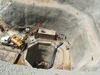
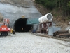
Tunnelling at Tsankov Kamak
18 July 2006Four tunnels were excavated as part of the Tsankov Kamak hydro power plant in Bulgaria
Groundbreaking began earlier this year for the Lyaskovo Road tunnel, the last tunnel at the Tsankov Kamak hydro power plant in Bulgaria. This project, which started in 2004, is located at the Vacha hydro power cascade on the Vacha river in the Rhodope Mountains, near the town of Smolyan on the border with Greece, about 250km south east of Sophia.
Tsankov Kamak is designated as a CO2 reduction project within the scope of the Kyoto Protocol mechanisms. Emission certificates generated by the plant will be transferred to the Austrian Carbon Credit programme via the Joint Implementation Mechanism (JI).
The client and project investor is the Natsionalna Elektricheska Kompania (NEK), Bulgaria’s national electric company. The work will be carried out by an Austrian industrial group led by va-tech Hydro, and includes Verbundplan (now Pöyry Energy GmbH) for engineering/project management and Alpine Mayreder for the civil works, including tunnelling.
VA Tech Hydro, now a member of the andritz group, is responsible for the supply of the electro-mechanical equipment like penstocks, gates, water turbines and generators, including mechanical and electrical balance of plant. The total investment is about h200M (US$250.8M), which covers civil works, engineering and the complete electromechanical package. Financing was arranged by VA Tech Finance and is entirely funded by the Austrian side.
The contract involves the construction of a 125m-high arch dam and an 80MW hydro power plant, with a standard production of 185GWh/year. The reservoir will have a volume of 111Mm3 and the power station will be located downstream, above ground on the left bank. The intake water tunnel, approximately 600m long, will be driven conventionally and will partly cut across a geologically problematic zone. An area of approximately 60,000m2 must be sealed off around the intake structure in the Gashnia Valley due to this area’s geological features.
The whole project will provide work for up to 1200 people during the four-year construction period.
Tunnel programme
The design of this project called for the building of four tunnels: the by-pass road tunnel as part of the temporary road connection, the diversion tunnel, the penstock tunnel with a vertical shaft, and the Lyaskovo Road tunnel.
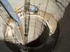
With a height of 125m and a crest length of 457m, the double curvature concrete arch dam will close off the Vacha Valley. The river will be diverted through a 500m tunnel and the public road will run through a 200m road tunnel in the dam area during the construction period. In addition to the intake structure, the intake waterway consists of a 60m vertical shaft and a 530m horizontal pressure tunnel with a 10% inclination. Steel lining will be required for the entire intake waterway. The water will power two Francis turbines and flow through a stilling section back into the Vacha river, which will be in the tailrace channel.
The 197m by-pass road tunnel was completed in accordance with the Verbundplan design. It was executed by the New Austrian Tunnelling Method in only 100 days. Drilling, blasting, excavating and lining operations were carried out as a continuous process, on a two-shift programme by fifteen workers on each shift.
The tunnelling and construction equipment for all tunnelling work was sourced by Alpine Mayreder Bau GmbH, Salzburg and Alpine Bulgaria AD from many locations around the world including Finland, Sweden, Germany, Switzerland, Russia, US and Bulgaria.
Diversion tunnel (length: 49m)
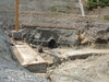
To reach the portal of the tunnel it was necessary to construct an access road. First a temporary pipe bridge was erected on the right-hand side of the river, close to the diversion tunnel outlet, to obtain access to the portal. Daily maintenance of the pipe bridge is necessary due to output from operations at the Devin hydro power plant.
Where it was not possible for excavation works for the diversion tunnel outlet portal to be carried out conventionally, drilling and blasting methods were used. Slope protection consisting of a 6cm layer of sulphatresistant shotcrete C20/25 was installed. While excavation of the portal was being carried out, the protection dam was built. Rock material from the portal excavation and the blasting operations at Road No.8 was used as fill for the dam. The dam was constructed in accordance with the technical specifications. After finishing excavation works at the tunnel outlet portal, the first face drilling was completed as follows:
•Survey and mark tunnel face and axis.
•Horizontal drilling and grouting of 3m anchors in a single row.
•Complete face drilling with a drilling length of 2m.
•Loading and blasting.
After excavating approximately 5m, the steel trusses were installed. After installation and support of the steel truss, drilling and blasting works were carried out according to the New Austrian Tunnelling Method. The stability of rock formations after blasting operations in the area of the tunnel face was checked before further support measures were carried out.
In normal rock conditions it was possible to proceed with conventional drilling and blasting. In bad rock conditions, support measures such as pre-shotcreting and spot bolting with an anchoring system were necessary. The support measures were executed approximately 10-15m behind the actual tunnel face. They consisted of pre-shotcreting caves and geological overbreaks, fixing steel mesh, and applying a second shotcrete layer through the steel mesh. Processing the second pre-shotcrete layer was carried out wet-in-wet. Finally, anchorage according to the design was completed. This is the proposed working process until the breakthrough. It was not necessary to overwork the surface of the tunnel in respect of the hydrogeological conditions. The mix design for the shotcrete is the same as used in the road by-pass tunnel.
After erection of the temporary road, excavation works for the inlet portal were completed in the same way as described for the outlet portal. After finishing the excavation works for the portal, the underground excavation works were then started from the inlet towards the outlet. Materials for the shotcrete and concrete were delivered from the small batching plant located next to the old diversion tunnel outlet. Blasting materials were stored and managed in the blasting depot next to the small batching plant.
Penstock tunnel
To reach the Intake it was necessary to excavate the intake – open cut, approx 30.000m3 – and parts of Road Nr. 4. To reach the tunnel outlet area, the landslide and power house excavations had first to be completed. The works were carried out with excavators and trucks. Where those methods were not possible, drilling and blasting was used. Slope protection, from el 673.45m asl down to 659m, was carried out with shotcrete C20/25 in a thickness of 17-30cm. Mesh 6.5mm dia, 15/15 and rock bolts dia 25mm and 28mm were also used. After finishing the open cut excavation works at the inlet, work started immediately on the site installation and excavation for the shaft and bend. This began on 1 August 2005. Drill and blast operations were executed. After the blasting, checking and validation of rock formations, instant support measures for the met rock conditions were carried out. Subsequent processes were similar to those used on the diversion tunnel.
Following the power house excavation and support of the slopes, work started immediately on the site installation and tunnel excavation from the power house site. The underground excavation works then began at the outlet towards the intake.
Lyaskovo road tunnel (length: 882m)
To reach the entrance (South) portal of the Lyaskovo tunnel, it was necessary to first erect a temporary access road. On the exit (North) portal, two temporary access pipe bridges were also erected.
As with the other tunnels, excavation works for the portals will be carried out with excavators and bulldozers, but where that is not possible, drilling and blasting will be used. It is anticipated that excavation of the portal area will include the removal of a diluvium layer and strongly weathered rocks.
Slope protection will include two layers of shotcrete C20/25, with a thickness of 5cm for each layer, steel mesh dia 6.5mm; 15/15 cm; Steelclass A-I and reinforcement concrete rockbolts 25mm dia. Steelclass A-III, L = 3.00m will be used at intervals of 2m in both directions. The execution sequence for the portals is as follows:
•Excavation works to the top of the tunnel portal.
•Support for the slopes with shotcrete, wire mesh and rockbolts.
•Erection of the protective ditch.
•Mount first support ring. Then the next three rings will be added outside. Steel mesh, sieve and shotcrete will be mounted over.
•Begin excavation of the tunnel calotte (top heading of the tunnel profile) and support.
•After excavation of approx 50m of the upper side of the tunnel profile, begin excavation of the invert, the lower side.
•After excavation of the lower side, the lower parts of the steel rings and shotcrete to the bottom of the tunnel profile will be applied.
•For access to the face, a temporary loading platform will be erected from excavated material after each step.
Dewatering of the portal areas will be through a drainage system from river gravel. Under it, a drainage pipe ø100 will be mounted. The drainage pipes pass by the lowest part of the protective fence and reach to the dewatering ditches of the road.
After installation and support of the steel truss, normal drilling and blasting works will be carried out according the New Austrian Tunnelling Method. Installation of the support measures depends on the stability of the rock formations after blasting in the tunnel face area. The contractor’s engineer is responsible for determining the stability of the rock formations and the support measures required for the met rock conditions.
Excavation works in the portal from the Devin side should be finished completely before the tunnel breakthrough. After breakthrough, it may be necessary for the shotcrete to be restored according to the Execution Design.
Overcoming hazards
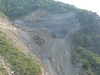
Projects like this are rarely accomplished without encountering difficulties at some stage. Tunnelling in the Rhodope Mountain range produces its own problems. Challenging geological issues, coupled with the unique design of the dam added further complications. For example, at some points, instead of finding rock – as indicated in the drawings – gravel was discovered. In other instances, it was the other way round – rock where gravel was expected. Things like this cannot always be predicted accurately during the design and budgeting phase of a project. Also, weather conditions in the mountainous locations were very severe and changeable. During the winter months, temperatures plummeted to 20º below zero!
In addition to coping with these problems, all works were, and are, being carried out with due regard to the safety and security of the environment – the plants, the trees, the wildlife and of course the air and the water. All machinery is equipped with the necessary filters, engines are controlled to prevent incidents like oil losses, and operations are confined to the area of the future lake as much as possible, to avoid spoiling the surrounding region.
Energy boost
The rehabilitation and integration of all works will improve the operation and water management of the other cascade hydro power stations. Environmentally, the plant will have no added impact on water flows, as the new construction site is located within the existing cascade of power stations. The construction of the missing interim section of the Dospat-Vacha hydro power cascade will contribute to the effective utilisation of the hydro energy potential along the Vacha river.
The existence and high flexibility of this hydro power plant will boost the operational efficiency of the power generating facilities connected to the electricity grid. It will contribute to the peak and peak-following load demand and frequency regulation. It will provide a fast reserve in case of a major unit failure and, above all, it will substantially reduce emissions potential.
Tsankov Kamak hydro power plant, with an estimated production of 185GWh/A, is extremely important to Bulgaria for energy-political reasons. It has already been decided to shut down the Bobov, Maritsa 3 and Rousse coal-fired power plants in 2008. They are to be replaced by the Tsankov Kamak plant, which is designated as a pilot project. The Austrian Ministry of Environment and Bulgaria have signed a bilateral agreement for the construction of the hydro power station as part of the Kyoto Protocol. The reduction of CO2 emissions caused by shutting down three coal-fired power stations in Bulgaria and the construction of the Tsankov Kamak HPP by 2008 will be used by Austria as a basis to verify the reduction of emissions under the Kyoto Protocol. On this basis, approximately 250,000 certificates per year will be generated by this power station from 2008 to 2012.
Author Info:
Sources: Alpine Mayreder Bau GmbH, Bulgarian Energy Observer, VA Tech Hydro, Verbundplan GmbH (Poyry Energy GmbH)
For further information contact Alpine Mayreder Bau GmbH, Alte Bundesstrasse 10, A-5071 Salzburg/Wals, Austria. Tel: +43 662 85 82 401. www.alpine.at or VA Tech Hydro, Penzinger Strasse 76, A-1141 Vienna. Tel: +43 189 1000. www.vatech-hydro.com
TablesTable 1